


Rig floor work puts you face-to-face with serious hazards every single day. One missed step in your rig floor safety checks could mean the difference between going home safely and ending up in a hospital—or worse.
This guide breaks down the essential man rider safety protocols that experienced drilling crews rely on to stay alive and injury-free. You’ll learn the exact drilling rig safety procedures that top-performing teams use, from pre-shift inspections that catch equipment failures before they happen to emergency response strategies that can save lives when things go sideways.
We’ll walk you through the most critical areas: proper rig floor hazard assessment techniques that help you spot danger before it spots you, the non-negotiable rig floor PPE requirements that protect you from head to toe, and the communication protocols that keep everyone on the same page when the pressure’s on.
Whether you’re new to the rig floor or looking to sharpen your safety game, these proven offshore drilling safety standards will help you work smarter, safer, and with confidence.
Pre-Shift Equipment Inspection Protocol
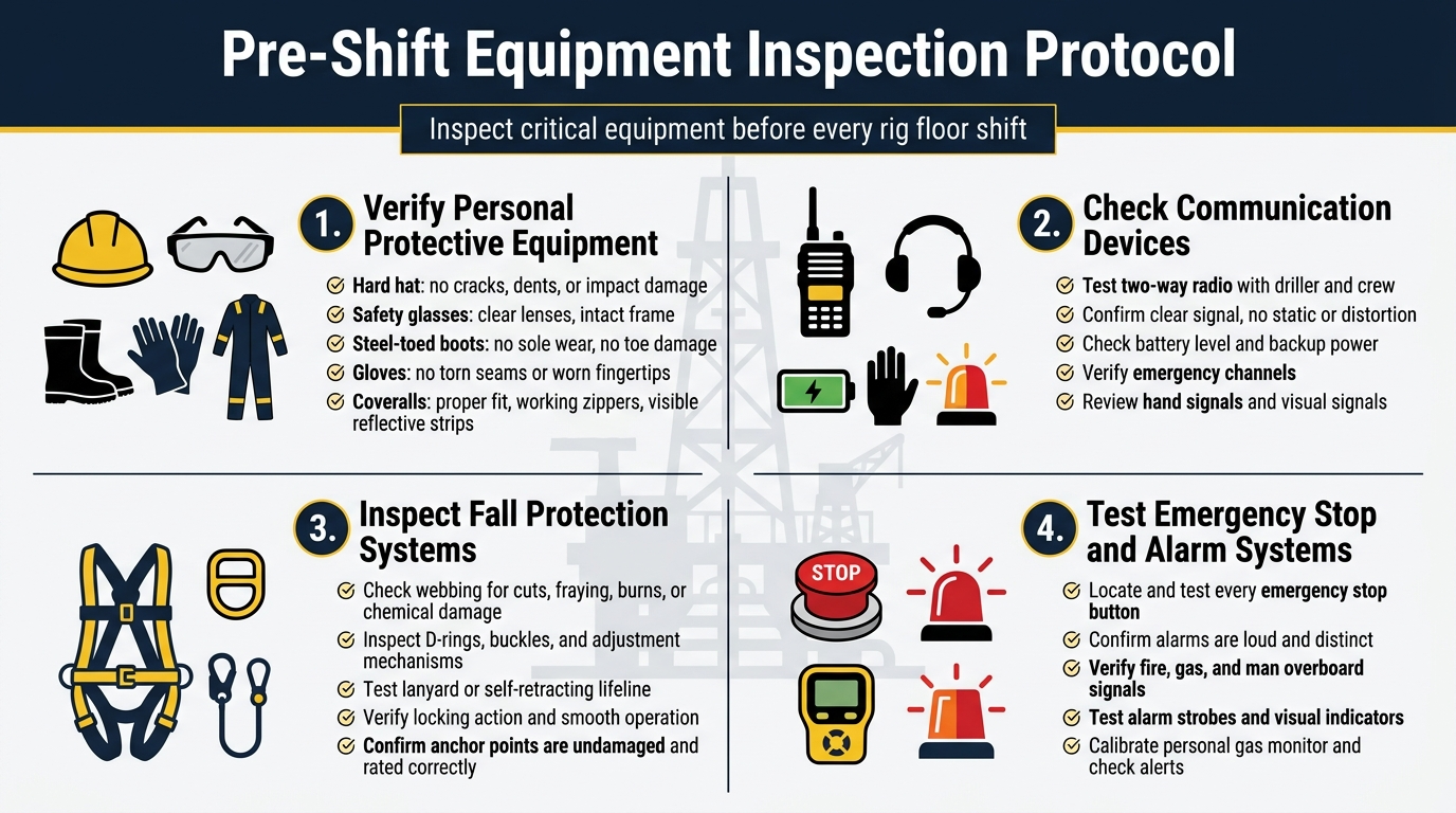
Verify Personal Protective Equipment Integrity and Proper Fit
Starting your shift without checking your PPE is like driving a car without testing the brakes first. Your personal protective equipment serves as your first line of defense against the countless hazards present on the drilling rig floor. Begin each rig floor safety check by examining your hard hat for cracks, dents, or signs of impact damage. The suspension system inside should move freely and hold your head securely without pressure points.
Your safety glasses need crystal-clear lenses without scratches that could impair vision during critical operations. Check the frame for loose screws or damaged temple pieces that might cause them to slip during work. Steel-toed boots require special attention – inspect the soles for excessive wear, loose stitching, or separation that could compromise protection. The steel toe cap should show no signs of cracking or deformation.

Work gloves often get overlooked, but torn seams or worn fingertips can expose you to cuts, chemicals, or burns. Replace any gloves showing significant wear. Your coveralls should fit properly without being too loose (creating snag hazards) or too tight (restricting movement). Check all zippers, buttons, and reflective strips to ensure they’re functioning and visible.
Check Communication Devices for Clear Signal Transmission
Communication breakdowns on drilling rigs can turn routine operations into life-threatening situations. Before stepping onto the rig floor, test every communication device you’ll be using. Start with your two-way radio by performing a radio check with the driller and other crew members. Verify that your voice transmits clearly without static or distortion.
Check the battery level indicator and confirm you have backup batteries or charging equipment readily available. Test the emergency channel frequencies to ensure you can reach supervisors and emergency responders when needed. If your rig uses hands-free communication systems, verify the headset fits securely and the microphone picks up your voice clearly.

- Shatterproof hidden display; without operating the walkie talkie to confirm; the hidden display enables teachers or othe…
- Rechargeable walkie talkie; equipped with a Type-C charging port and charging base; two charging methods increase the co…
- VOX hands-free; two way radio supports talking with members without pressing the PTT key; even when you are busy at work…
Hand signals remain important backup communication methods when radio systems fail or during high-noise operations. Review the standard hand signals with your crew and ensure everyone understands the emergency stop signal. Test any visual communication aids like signal lights or flags that might be used during lifting operations or adverse weather conditions.
Inspect Safety Harnesses and Fall Protection Systems
Fall protection equipment literally holds your life in its hands, making this inspection absolutely critical for man rider safety protocols. Examine every inch of your safety harness webbing for cuts, fraying, burns, or chemical damage. Pay special attention to stress points around the D-rings and buckles where wear typically occurs first.
Check all hardware components, including D-rings, buckles, and adjustment mechanisms. D-rings should rotate freely without binding, and buckles must lock securely while still allowing easy adjustment. Look for corrosion, cracks, or excessive wear on metal components that could lead to failure under load.

Inspect your lanyard or self-retracting lifeline for proper operation. Lanyards should show no signs of cuts or core exposure, while self-retracting devices should extend and retract smoothly without binding. Test the locking mechanism to ensure it engages properly during a sudden stop. Verify that your fall protection anchor points can support the required load ratings and remain free from damage or corrosion.
Test Emergency Stop Mechanisms and Alarm Systems
Emergency stop systems serve as your last line of defense when operations go wrong. Begin by locating all emergency stop buttons within your work area and testing their accessibility. Each button should be easily reachable and clearly marked with bright colors or signage. Press each emergency stop to verify it immediately shuts down the intended equipment.
Test general alarm systems to ensure they produce audible signals that can be heard above normal rig operations. Different alarm tones should be clearly distinguishable – fire alarms, gas detection alarms, and man overboard signals each require unique sounds. Verify that alarm strobes and visual indicators function properly for situations where noise levels make audio alarms ineffective.

- SAFETY FIRST: At HLWDFLZ, QUALITY IS OUR TOP PRIORITY. Long lasting, high-performance car emergency kits to ensure your …
- FAST INFLATE: In an emergency, when the tire is flat and running, you need this 12V, 250 PSI portable air pump. It provi…
- BUILT TO KEEP YOU SAFE: Our PVC insulation jumper cable leads with heat resistance, four giant alligator insulated rubbe…
Check your personal gas monitor if working in areas with potential hydrocarbon exposure. Calibrate the device according to manufacturer’s specifications and test all alarm functions. The monitor should alert you to dangerous gas concentrations well before they reach hazardous levels. Ensure you understand the different alarm patterns and know the appropriate response for each type of gas detection alert.
Rig Floor Hazard Assessment Procedures
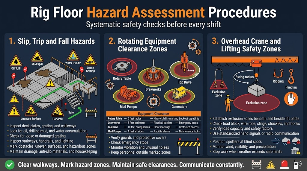
Identify slip, trip, and fall hazards on walking surfaces
Walking surfaces on rig floors present constant dangers that require systematic evaluation before every shift. Start by examining all deck plates, grating, and walkways for oil, drilling mud, or water accumulation that creates slippery conditions. Check for loose or damaged grating sections that could shift under weight, creating unexpected trip hazards.
Pay special attention to areas around the rotary table, pipe racks, and mud circulation systems where spills commonly occur. Look for worn anti-slip surfaces that have lost their effectiveness, especially near high-traffic zones like the driller’s cabin and tool storage areas. Inspect stairways and handrails for structural integrity and proper lighting coverage.
Document any uneven surfaces, protruding equipment, or temporary obstacles that workers might encounter during operations. Weather conditions significantly impact surface safety – rain, ice, or fog can transform routine pathways into serious hazards. Establish clear protocols for applying anti-slip materials and ensuring adequate drainage around work areas.
Create designated safe walkways and mark hazardous zones with highly visible barriers or warning signs. Regular housekeeping checks throughout the shift help maintain surface safety as conditions change with ongoing operations.
Evaluate rotating equipment clearance zones
Rotating equipment poses severe injury risks that demand careful zone assessment and management. Begin by identifying all rotating machinery including drawworks, rotary table, top drives, mud pumps, and generators. Establish minimum clearance distances based on manufacturer specifications and industry safety standards.
Mark danger zones around rotating equipment with permanent floor markings, barriers, or warning signs that remain visible under all lighting conditions. Verify that emergency stops are accessible and functional for each piece of rotating machinery. Check that guards and protective covers are properly installed and secured before equipment startup.
| Equipment Type | Minimum Clearance | Warning Zone | Access Controls |
|---|---|---|---|
| Rotary Table | 6 feet radius | High-visibility marking | Lockout capability |
| Drawworks | 8 feet perimeter | Physical barriers | Emergency stops |
| Top Drive | 10 feet swing radius | Floor markings | Restricted access |
| Mud Pumps | 4 feet all sides | Audible alarms | Maintenance locks |

Monitor equipment vibration levels and unusual noises that might indicate mechanical problems leading to equipment failure. Ensure all personnel understand the specific hazards associated with each rotating system and know proper approach procedures when equipment operation is necessary.
Assess overhead crane and lifting operations safety zones
Overhead lifting operations create dynamic hazard zones that shift based on load movement and crane positioning. Before any lifting activity begins, establish exclusion zones beneath and adjacent to the intended lift path. Calculate swing radius for mobile cranes and verify adequate clearance from structures, equipment, and personnel areas.
Check load block positioning and wire rope condition for signs of wear, kinking, or damage that could cause load failure. Verify that lifting equipment capacity matches or exceeds the planned load weight with appropriate safety factors. Inspect rigging hardware including slings, shackles, and hooks for proper certification and visible defects.
Establish communication protocols between crane operators and ground personnel using standardized hand signals or radio procedures. Position spotters at critical locations to monitor blind spots and potential conflicts with ongoing rig operations. Verify that all personnel in the area understand emergency procedures if equipment fails or loads become unstable.
Weather conditions significantly affect lifting operations – wind speeds, visibility, and precipitation can transform routine lifts into dangerous situations. Monitor environmental factors continuously and establish shutdown criteria when conditions exceed safe operating limits. Coordinate lifting activities with other rig floor operations to prevent simultaneous hazards that could overwhelm emergency response capabilities.
Personal Protective Equipment Verification Standards

Confirm hard hat certification and impact resistance
Safety headgear serves as the first line of defense against falling objects and overhead hazards on drilling operations. Check that your hard hat displays current ANSI Z89.1 certification markings, typically found on the inside shell near the rim. Type I helmets protect against vertical impacts from above, while Type II models offer additional side impact protection – essential for rig floor environments where hazards come from multiple directions.

- 100% Matte
- Imported
- Constructed from ABS material — Strong, yet ultra-light for seemingly weightless protection
Inspect the shell for stress cracks, dents, or UV damage that compromises structural integrity. Pay attention to the suspension system inside, ensuring webbing remains secure and properly adjusted. Replace any helmet showing signs of impact damage, even minor ones, as the protective capacity becomes unpredictable after contact with objects.
Validate safety glasses and face protection coverage
Eye protection requirements vary based on specific rig floor tasks and environmental conditions. Standard safety glasses must meet ANSI Z87.1 standards, clearly marked on the frame or lens. Side shields become mandatory when working around grinding operations, chemical exposure, or high-velocity debris risks.

- ANSI Z87.1+ AND CSA Z94.3 CERTIFIED SAFETY: Meets both US and Canadian safety standards (ANSI Z87.1+ AND CSA Z94.3) to s…
- ANTI-FOG AND SCRATCH-RESISTANT LENS: Features premium ANSI anti-fog and scratch-resistant coatings for long-lasting clar…
- UV PROTECTION WITH CRYSTAL CLEAR VISION: Class 1 optical lenses ensures distortion-free vision and ANSI U6 rated UV prot…
For welding operations or intense light exposure, switch to appropriate shade-rated protective eyewear. Anti-fog coatings prove invaluable in humid offshore conditions where vision impairment creates serious safety risks. Prescription safety glasses require the same impact ratings as standard protective eyewear – regular prescription glasses never substitute for proper safety equipment.
Ensure steel-toed boots meet compression standards
Footwear protection standards for rig floor operations demand boots rated for 75-pound compression loads and 30-foot pound impact resistance. Look for ASTM F2413 markings on the boot tongue or inside collar. Steel-toed protection extends beyond just the toe area – metatarsal guards shield the upper foot from dropped objects.

Slip-resistant outsoles with deep tread patterns provide traction on wet, oily surfaces common to drilling environments. Electrical hazard protection becomes critical around powered equipment, requiring boots rated for 18,000 volts. Regular inspection reveals sole separation, worn treads, or compromised safety features that necessitate immediate replacement.
Check glove material compatibility with work tasks
Different drilling operations require specific glove materials matched to chemical exposure risks and dexterity needs. Nitrile gloves resist petroleum products and drilling fluids while maintaining grip strength. Leather work gloves handle rough materials and provide cut resistance for handling pipe and equipment.

- 【EXCELLENT MATERIAL AND DESIGN】-This heavy duty gloves is made of 100% split cowhide leather and 100% cotton lined, whic…
- 【WIDE RANGE OF APPLICATIONS】-This husky gloves can be used in many works: garden work, welding, construction, farm, ranc…
- 【EXCELLENT THORN PROOF AND WEAR RESISTANCE】-You can use it when weed pulling, using weed wacker, digging, sowing, mixing…
Chemical compatibility charts guide selection when working with specific drilling compounds or cleaning agents. Inspect gloves for punctures, tears, or chemical degradation before each use. Cut-resistant gloves rated ANSI A2 through A9 provide varying protection levels – match the rating to your specific cutting hazards.
Verify hearing protection effectiveness levels
Rig floor noise levels frequently exceed 85 decibels, requiring hearing protection with appropriate Noise Reduction Ratings (NRR). Disposable foam earplugs typically provide 25-33 NRR when properly inserted, while reusable silicone plugs offer consistent protection with proper cleaning. Over-ear muffs deliver higher protection levels, often 20-30 NRR, and work well with hard hats.

- 34 dB NRR — Proven, Compact & Trusted for Over 10 Years: Since 2013, we’ve designed sleeker, lighter safety earmuffs wit…
- BREAK-IN TO UNLOCK COMFORT & CUSTOMIZED FIT: For best noise reduction, these passive noise cancelling ear muffs fit snug…
- ESSENTIAL GEAR FOR LOUD EVENTS & SENSORY NEED: Pro For Sho 34 dB NRR noise reduction ear muffs deliver serious protectio…
Electronic hearing protection allows normal conversation while automatically dampening harmful noise levels. Test electronic units before each shift to confirm battery life and proper amplification. Combine earplugs with earmuffs for maximum protection in extremely loud environments, following manufacturer guidelines for dual protection calculations.
Communication and Emergency Response Readiness
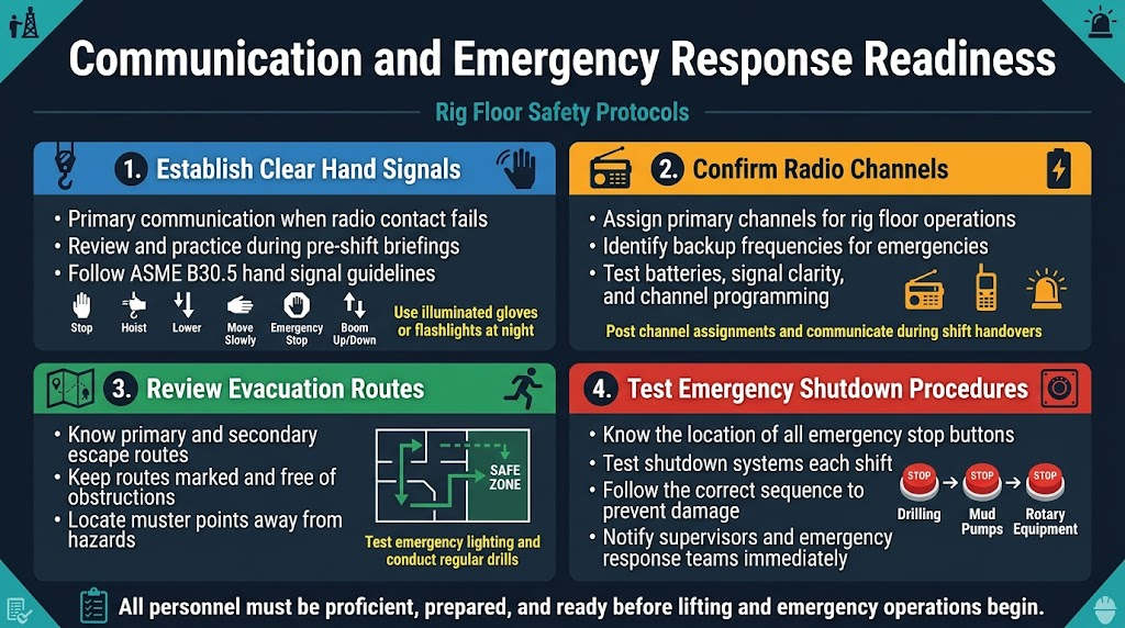
Establish Clear Hand Signals with Crane Operators
Hand signals serve as the primary communication method between rig floor personnel and crane operators, especially when radio communication fails or ambient noise makes verbal contact impossible. Standard hand signals must be reviewed and practiced during pre-shift briefings to ensure consistency across all crew members. The American Society of Mechanical Engineers (ASME) B30.5 standard provides comprehensive hand signal guidelines that should be followed religiously on drilling rigs.
Critical hand signals include stop, hoist, lower, move slowly, emergency stop, and boom up/down commands. Each signal must be deliberate, exaggerated, and clearly visible to the crane operator. Night operations require additional considerations, such as using illuminated gloves or flashlights to maintain signal visibility. All personnel involved in lifting operations should demonstrate proficiency in these signals before beginning work.
Confirm Radio Channel Assignments and Backup Frequencies
Effective drilling rig communication protocols depend on clearly designated radio channels for different operational areas. Primary channels should be assigned for rig floor operations, with dedicated backup frequencies identified for emergency situations. Channel assignments must be communicated during shift handovers and posted in visible locations throughout the work area.
Radio equipment checks should verify battery levels, signal clarity, and proper channel programming. Backup communication devices, including satellite phones or emergency beacons, must be tested and their locations known to all personnel. Communication logs should document any equipment malfunctions or signal interference issues that could compromise safety during critical operations.
Review Evacuation Routes and Muster Point Locations
Emergency evacuation procedures form a critical component of rig floor safety protocols. All personnel must know multiple evacuation routes from their work areas to designated muster points. Primary and secondary escape routes should be clearly marked and kept free of obstructions at all times.
Muster point locations must be positioned at safe distances from potential hazards, including wellheads, fuel storage areas, and heavy equipment. Regular drills help reinforce evacuation procedures and identify potential bottlenecks or safety concerns. Emergency lighting systems along evacuation routes require regular testing to ensure functionality during power outages or low-visibility conditions.
Test Emergency Shutdown Procedures and Protocols
Emergency shutdown systems represent the last line of defense against catastrophic incidents on drilling rigs. All rig floor personnel must understand the location and operation of emergency stop buttons, including those controlling drilling operations, mud pumps, and rotary equipment. These systems should be tested during each shift to verify proper functionality.
Shutdown procedures must be practiced until they become second nature, with clear protocols established for different emergency scenarios. Personnel should know which systems to shut down first and understand the sequential order of operations to prevent equipment damage or secondary hazards. Emergency response protocols should include immediate notification procedures for supervisory personnel and emergency response teams.
Lifting and Rigging Safety Validation
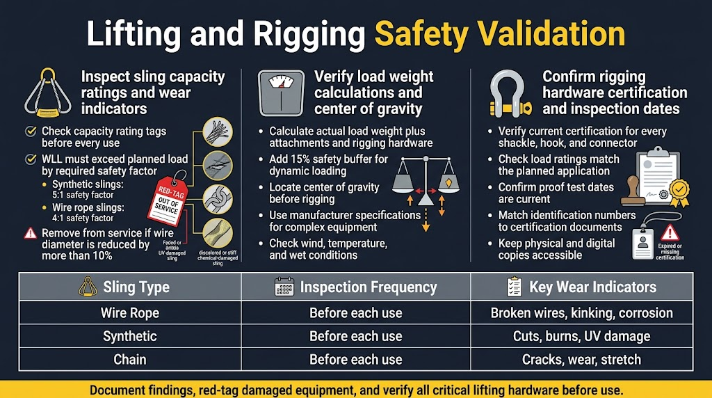
Inspect sling capacity ratings and wear indicators
Every sling used in man rider operations carries critical information that can mean the difference between a safe lift and a catastrophic failure. Check the capacity rating tags on each sling before every use – these aren’t just suggestions, they’re your lifeline. The working load limit (WLL) must clearly exceed your planned load by the required safety factor, typically 5:1 for synthetic slings and 4:1 for wire rope slings.
Visual inspection reveals stories that numbers can’t tell. Look for frayed wire strands, cuts in synthetic materials, or distortion in hardware components. Any sling showing more than 10% reduction in wire diameter should be immediately removed from service. For synthetic slings, UV damage appears as fading or brittleness, while chemical damage shows as discoloration or unusual stiffness.
Document your findings in the lifting and rigging safety guidelines checklist. Red-tagged equipment stays out of service until properly inspected by certified personnel. Remember, a damaged sling doesn’t just risk the load – it endangers every person on the rig floor.
| Sling Type | Inspection Frequency | Key Wear Indicators |
|---|---|---|
| Wire Rope | Before each use | Broken wires, kinking, corrosion |
| Synthetic | Before each use | Cuts, burns, UV damage |
| Chain | Before each use | Cracks, wear, stretch |
Verify load weight calculations and center of gravity
Accurate load calculations separate professional riggers from accidents waiting to happen. Start by calculating the actual weight of your load, including all attachments, rigging hardware, and safety equipment. Add a 15% safety buffer to account for dynamic loading during lifting operations.
Center of gravity calculations demand precision. An off-center load creates unequal stress distribution across lifting points, potentially overloading individual slings. Use the manufacturer’s specifications for complex equipment, and physically locate the center of gravity for irregular loads before rigging begins.
Consider environmental factors that affect your calculations. Wind loading adds significant stress to large surface area components, while temperature changes can affect material properties. Wet conditions increase weight and reduce friction coefficients for certain materials.
Document your calculations and have them verified by a second qualified person. This double-check system catches mathematical errors that could compromise drilling rig safety procedures. Keep these records with your lift plan for post-operation review and continuous improvement of your man rider safety protocols.
Confirm rigging hardware certification and inspection dates
Certification paperwork isn’t bureaucratic busy work – it’s proof that your hardware can handle the forces you’re about to apply. Every shackle, hook, and connecting device must carry current certification from approved testing facilities. Check that load ratings match your planned application and verify that proof test dates fall within required intervals.
Inspection certificates should accompany each piece of critical hardware. These documents show testing history, any repairs or modifications, and remaining service life. Missing or expired certifications mean the hardware stays grounded until properly re-certified through approved channels.
Physical inspection stamps or markings provide quick field verification of hardware status. Look for clear identification numbers that match certification documents, and check for any signs of tampering or modification. Painted or welded-on markings that obscure original manufacturer stamps raise immediate red flags.
Store certification documents in weather-protected locations but keep copies readily accessible during operations. Digital backups prevent loss of critical paperwork, but always maintain physical copies as backup. Your rig floor hazard assessment procedures should include regular audits of certification status for all lifting hardware to prevent expired equipment from entering service rotation.
Environmental and Weather Condition Monitoring
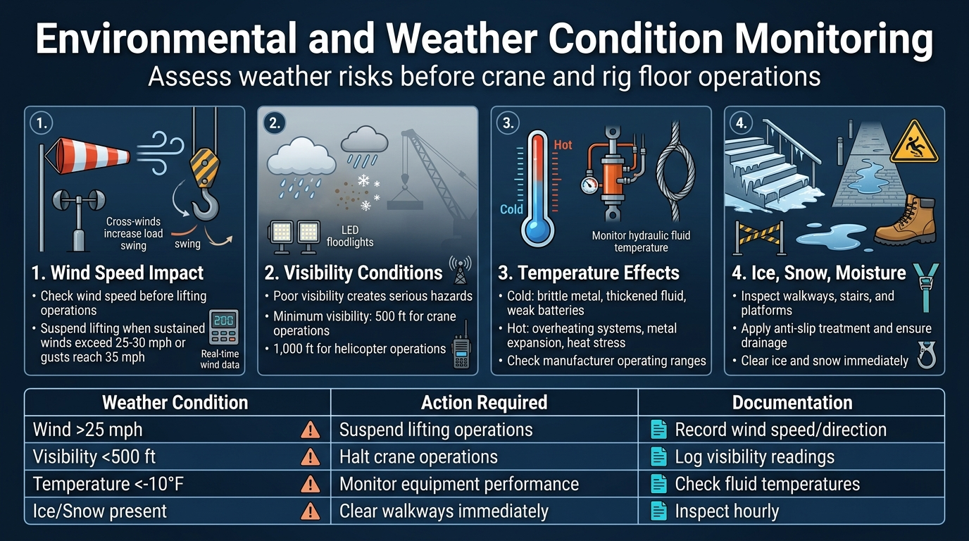
Assess Wind Speed Impact on Crane Operations
Wind conditions directly affect crane stability and load control during rig floor operations. Check wind speed readings before starting any lifting operations, especially when working with man rider safety protocols. Most drilling rig safety procedures require operations to cease when sustained winds exceed 25-30 mph or gusts reach 35 mph.
Pay attention to wind direction changes that can cause unexpected load swinging. Cross-winds create the most dangerous conditions for personnel baskets and equipment lifts. Document wind readings every hour and immediately before critical lifts. Modern rigs equipped with wind monitoring systems should display real-time data on control panels.
Evaluate Visibility Conditions for Safe Equipment Operation
Poor visibility creates serious hazards during rig floor safety checks and man rider operations. Fog, heavy rain, snow, or dust storms can reduce visibility below safe operating limits. Standard offshore drilling safety standards require minimum visibility of 500 feet for crane operations and 1,000 feet for helicopter operations.
Install adequate lighting systems and ensure backup power sources function properly. LED floodlights should illuminate work areas without creating glare or shadows that obscure hazards. Radio communication becomes even more critical during low-visibility conditions. Establish clear protocols for suspending operations when visibility drops below acceptable levels.
Monitor Temperature Effects on Equipment Performance
Extreme temperatures affect equipment reliability and worker safety. Cold weather causes metal components to become brittle, hydraulic fluids to thicken, and batteries to lose capacity. Hot conditions can lead to overheating of hydraulic systems, expansion of metal components, and heat stress for personnel.
Check equipment manufacturer specifications for operating temperature ranges. Monitor hydraulic fluid temperatures and adjust operation speeds during extreme weather. Steel wire rope contracts in cold weather, potentially affecting load calculations. Keep backup equipment ready when temperatures approach operational limits.
Check for Ice, Snow or Moisture Creating Slip Hazards
Wet or frozen surfaces create deadly slip hazards on rig floors. Inspect all walkways, stairs, and work platforms for ice formation, snow accumulation, or water pooling. Pay special attention to areas around washdown stations, mud pits, and equipment that generates condensation.
Apply anti-slip treatments to metal surfaces and ensure proper drainage systems function correctly. Remove ice and snow immediately using approved methods – never use steam or hot water that can create flash ice. Install temporary barriers around particularly hazardous areas until conditions improve. Check that safety harness anchor points remain ice-free and accessible.
| Weather Condition | Action Required | Documentation |
|---|---|---|
| Wind >25 mph | Suspend lifting operations | Record wind speed/direction |
| Visibility <500 ft | Halt crane operations | Log visibility readings |
| Temperature <-10°F | Monitor equipment performance | Check fluid temperatures |
| Ice/Snow present | Clear walkways immediately | Inspect hourly |
Tool and Equipment Operational Safety Verification

Test Power Tool Grounding and Electrical Safety Systems
Electrical hazards on drilling rigs present serious risks to man rider safety protocols. Before each shift, verify that all power tools feature proper three-prong grounding plugs and intact cord insulation. Check ground fault circuit interrupter (GFCI) protection systems are functioning by pressing test and reset buttons. Any tool displaying frayed wires, exposed conductors, or damaged housing must be tagged out immediately.
Inspect extension cords for cuts, kinks, or water damage that could create shock hazards. Power tools used in wet conditions require specialized waterproof housings and marine-grade connections. Test voltage levels match tool specifications – mismatched voltage can cause equipment failure or dangerous overheating during rig floor operations.
Verify Pneumatic Tool Pressure Settings and Hose Integrity
Pneumatic systems power critical drilling equipment, making pressure verification essential for safe operations. Check air pressure gauges match manufacturer specifications before connecting tools. Over-pressurized systems can cause catastrophic hose failures, while under-pressure reduces tool effectiveness and increases injury risk.
Examine air hoses for cracks, bulges, or worn fittings that indicate potential blowout zones. Pay special attention to connection points where stress concentrates. Replace any hose showing signs of deterioration or damage. Verify quick-disconnect couplings engage fully and release properly – malfunctioning connections can cause tools to separate unexpectedly under pressure.
Test pressure relief valves and safety shutoffs respond correctly to prevent dangerous pressure buildup. Document pressure readings and any maintenance performed as part of comprehensive drilling rig safety procedures.
Inspect Manual Tools for Damage and Proper Maintenance
Hand tools receive heavy use in demanding rig environments, making regular inspection critical. Check hammer heads for cracks or loose handles that could fail during use. Worn striking surfaces create unpredictable rebound patterns and reduce effectiveness. Examine wrenches for bent jaws, cracked bodies, or worn adjustment mechanisms that compromise grip strength.
Verify cutting tools maintain sharp edges without chips or nicks. Dull blades require excessive force, increasing slip potential and fatigue. Look for proper tool storage and organization – scattered tools create trip hazards and damage risks. Clean tools of mud, grease, or debris that can cause grip failures.
Replace tools showing excessive wear or damage immediately. Maintain detailed records of tool condition and replacement schedules to prevent equipment failures during critical operations.
Confirm Specialty Equipment Calibration and Functionality
Specialized drilling equipment requires precise calibration for safe operation. Verify torque wrenches display accurate readings within manufacturer tolerances. Out-of-calibration torque tools can over-tighten connections, causing equipment failure, or under-tighten, creating leak hazards.
Test measuring instruments like gauges, levels, and alignment tools for accuracy. Environmental conditions on rigs can affect calibration, particularly temperature extremes and vibration. Check calibration certificates remain current and schedule recalibration according to manufacturer recommendations.
Confirm safety devices like load blocks, sheaves, and lifting accessories undergo proper inspection intervals. Test emergency stops, limit switches, and safety interlocks function correctly. Any specialty equipment showing calibration drift or functional problems requires immediate removal from service until proper maintenance restores safe operating parameters.
Watch this video
References and Resources
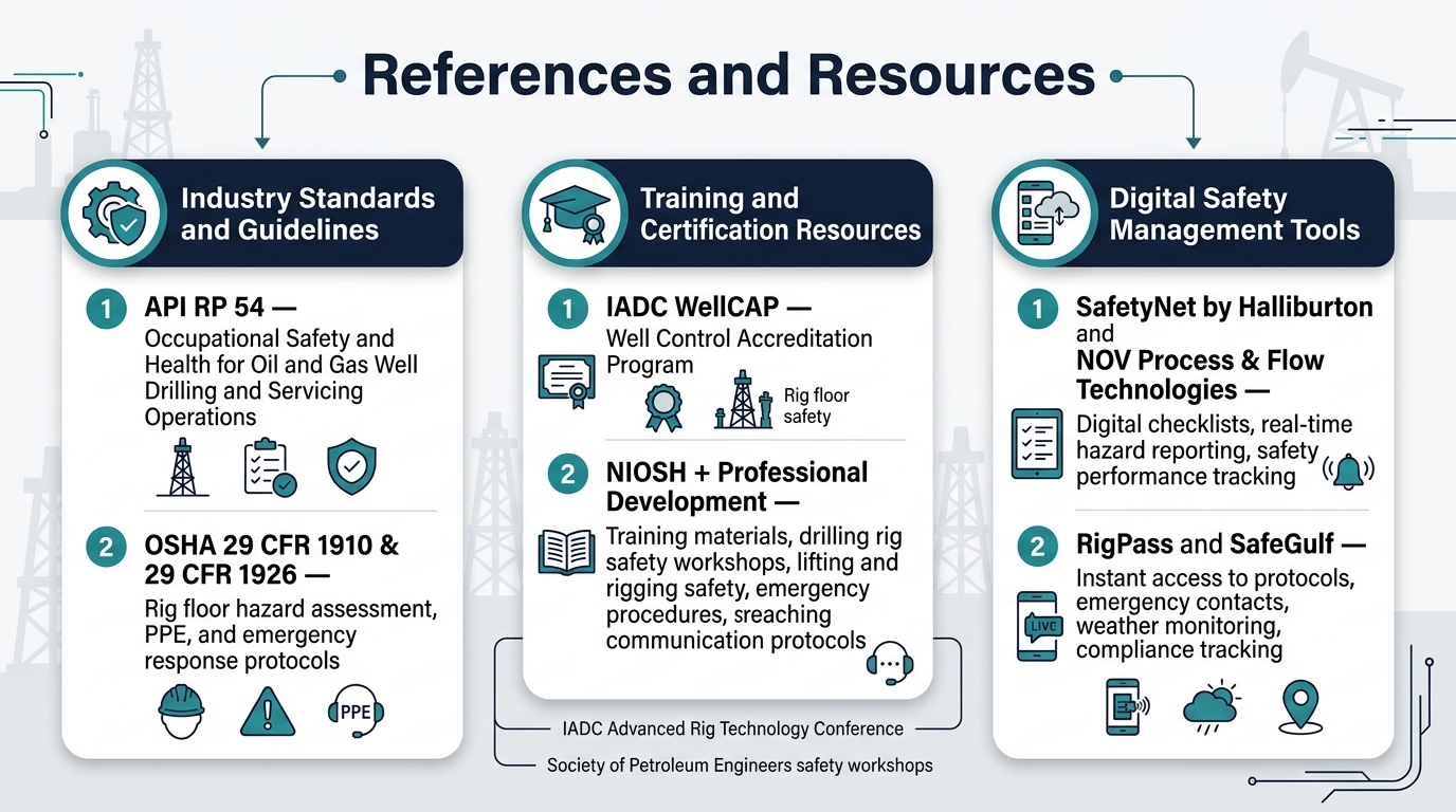
Industry Standards and Guidelines
The American Petroleum Institute (API) provides comprehensive standards for drilling rig safety procedures through API RP 54 – Occupational Safety and Health for Oil and Gas Well Drilling and Servicing Operations. This document serves as the foundation for establishing rig floor safety checks and man rider safety protocols across the industry. The International Association of Drilling Contractors (IADC) also maintains extensive safety guidelines through their Accident Statistics Program and Health, Safety & Environment Committee resources.
The Occupational Safety and Health Administration (OSHA) regulations 29 CFR 1910 and 29 CFR 1926 establish mandatory requirements for offshore drilling safety standards and general industry safety protocols. These regulations specifically address rig floor hazard assessment procedures, personal protective equipment requirements, and emergency response protocols that every man rider must understand and follow.
Training and Certification Resources
The International Association of Drilling Contractors offers WellCAP (Well Control Accreditation Program) certification, which includes critical components of rig floor safety and emergency procedures. The National Institute for Occupational Safety and Health (NIOSH) provides specialized training materials for drilling rig workers through their Criteria for a Recommended Standard: Occupational Exposure to Refractory Ceramic Fibers publication.
Professional development opportunities include the IADC Advanced Rig Technology Conference and the Society of Petroleum Engineers safety workshops. These programs focus on lifting and rigging safety guidelines, drilling rig emergency procedures, and advanced rig floor communication protocols.
Digital Safety Management Tools
Modern safety management platforms like SafetyNet by Halliburton and NOV’s Process & Flow Technologies provide digital checklists for man rider equipment inspection and real-time hazard reporting systems. These tools integrate with existing rig management software to track safety performance and ensure compliance with rig floor PPE requirements.
Mobile applications such as RigPass and SafeGulf offer instant access to safety protocols, emergency contact information, and weather monitoring data directly on rig floors. These platforms support the implementation of comprehensive drilling rig safety procedures while maintaining detailed records of safety check completion and compliance tracking.
Conclusion
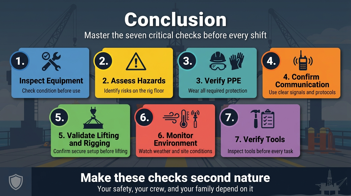
Your safety on the rig floor depends on mastering these seven critical checks before every shift. From thoroughly inspecting equipment and assessing hazards to verifying your PPE and establishing clear communication protocols, each step builds a protective barrier between you and potential danger. The lifting and rigging validation, environmental monitoring, and tool verification rounds complete your safety arsenal, giving you the confidence to work effectively in one of the most demanding industrial environments.
Don’t treat these safety checks as just another box to tick off your daily routine. Make them second nature, because your life and the lives of your crew members depend on getting them right every single time. Start implementing these protocols immediately, and encourage your teammates to do the same. Remember, a safe rig floor is everyone’s responsibility, but it starts with each individual taking these checks seriously. Your family wants you home safe – make sure these seven safety checks help get you there.