

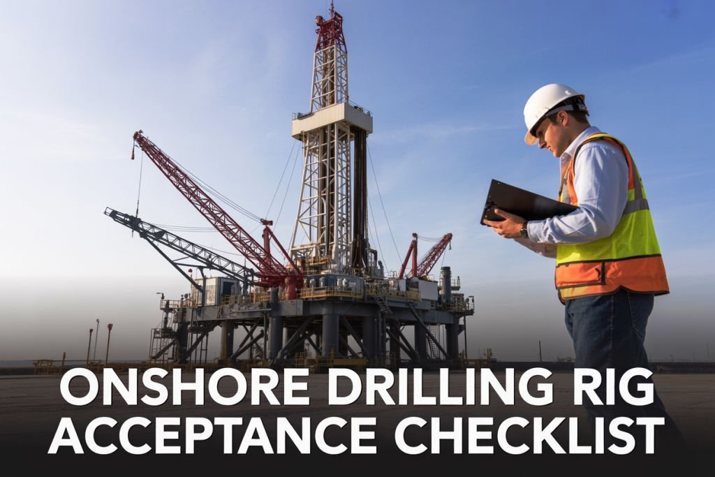

If you’re a drilling superintendent, rig manager, or HSE coordinator getting ready to mobilize an onshore drilling rig, the acceptance process is one of the most critical steps you’ll handle before a single bit hits the ground. With a thorough onshore drilling rig acceptance checklist, you can confirm that every system on the rig is fit for purpose, compliant with safety standards, and ready to run without surprises.
In this guide, we’ll walk through the key areas you need to cover — starting with structural and mechanical integrity checks to catch physical deficiencies early, well control equipment and blowout prevention systems to make sure your last line of defense is fully operational, and safety and environmental compliance standards that protect your crew and keep you on the right side of regulations.
Whether you’re doing a first-time rig acceptance or running a pre-spud inspection on a rig you’ve worked with before, this checklist gives you a practical, no-guesswork framework to work through.
Understanding the Purpose of a Rig Acceptance Checklist

Why Acceptance Checks Prevent Costly Downtime
Bringing a drilling rig onto location without a thorough acceptance check is a bit like buying a used car without looking under the hood — you might get away with it, but the odds are not in your favor. Rig acceptance checks exist to catch problems before they snowball into expensive, time-consuming headaches on the job site.
Downtime on an onshore drilling rig is brutal from a cost perspective. Depending on the rig class and the contract terms, a single day of unplanned downtime can run anywhere from tens of thousands to hundreds of thousands of dollars. That figure does not even account for the ripple effects — delayed well programs, crew overtime, supply chain disruptions, and potential contractual penalties.
Here is what a proper rig acceptance checklist actually prevents:
- Mechanical failures during spud-in — Catching worn-out components, faulty gauges, or improperly assembled equipment before operations begin
- Well control incidents — Identifying gaps in blowout prevention equipment before pressure is ever applied to the wellbore
- Regulatory shutdowns — Ensuring all safety systems meet local and international standards so the regulator does not pull the plug mid-operation
- Crew injuries — Spotting unsafe working conditions, missing safety interlocks, or malfunctioning lifting equipment before people are put at risk
- Environmental violations — Verifying that secondary containment, spill control measures, and waste management systems are properly in place
Think of the acceptance checklist as your single best investment of time before a rig ever turns to the right. An hour spent reviewing documentation and walking the rig floor can save weeks of unplanned standby time later in the well program.
Key Stakeholders Involved in the Acceptance Process
A rig acceptance inspection is never a one-person job. It pulls in multiple parties, each bringing a different set of eyes and a different area of accountability to the table.
Operator Representatives
The operator — the company that holds the drilling license and is ultimately responsible for the well — typically leads the acceptance process. Their drilling superintendent or company man will work through the checklist alongside the rig contractor to confirm that the equipment meets the contracted specifications and is fit for the intended well program.
Rig Contractor Personnel
The rig contractor brings their own technical team to the inspection. The rig manager, toolpusher, and chief mechanic or electrician are usually present to walk through their respective systems. They are accountable for demonstrating that the rig is mechanically and operationally ready.
Third-Party Inspection Companies
On most major well programs, operators bring in a certified third-party inspection firm. These are independent engineers or inspection bodies with no financial stake in moving the rig faster. Their job is to give an honest assessment, and their sign-off carries significant weight with both the operator and the regulator.
Regulatory and Government Bodies
Depending on the jurisdiction, a government inspector or representative from the relevant energy authority may need to be present for — or at least notified of — the acceptance inspection. In many countries, operating without this regulatory review is simply not an option.
Health, Safety, and Environment (HSE) Teams
Both the operator and the contractor should have their HSE representatives involved. These individuals are specifically focused on safety systems, emergency response equipment, environmental controls, and compliance with applicable standards like API, ISO, or local government regulations.
| Stakeholder | Primary Focus Area |
|---|---|
| Operator Representative | Contract compliance, well program fit |
| Rig Contractor (Toolpusher / Rig Manager) | Mechanical and operational readiness |
| Third-Party Inspector | Independent technical verification |
| Regulatory Body | Legal and statutory compliance |
| HSE Team | Safety systems, environment, emergency response |
Getting all of these parties aligned from day one sets a collaborative tone for the entire well campaign. When everyone has signed off on the same document, there is far less room for finger-pointing if something goes sideways later.
When to Conduct a Rig Acceptance Inspection
Timing is everything with rig acceptance. Conducting the inspection too late — when the rig is already rigged up at location and the clock is ticking — puts enormous pressure on the team to rush through critical checks. Conducting it too early, before all equipment has been assembled and function-tested, means you will need to come back and do it again anyway.
Pre-Mobilization Inspection
A preliminary inspection is often carried out at the rig yard or staging area before the rig moves to location. This is a good opportunity to review documentation, check major components, and identify any obvious deficiencies that can be repaired before mobilization. It saves everyone from the embarrassment and cost of trucking a rig to a remote location only to discover it needs major work.
Post-Rigging-Up Inspection
Once the rig has been fully rigged up at the drill site — drawworks in place, BOP stack assembled, mud system connected, and all electrical systems energized — a final walk-through inspection should be completed before spud-in. This is the definitive check that confirms everything is working as a complete, integrated system.
Trigger Events That Require a New Inspection
Beyond the initial acceptance, certain events should automatically trigger a fresh inspection or at least a partial re-inspection:
- Rig move between wells — Especially if the rig has been disassembled and reassembled
- Major component replacement — Swapping out a top drive, hoisting system, or BOP stack requires re-verification of the replaced equipment
- Incident or near-miss — Any event that may have compromised the structural or mechanical integrity of the rig
- Extended idle periods — If a rig has been stacked for six months or more, a full re-acceptance is typically expected before returning to service
- Change in regulatory requirements — If new standards have come into effect during the rig’s deployment, compliance must be re-confirmed
A good practice is to build the acceptance inspection schedule directly into the well program from the beginning, treating it as a non-negotiable milestone with clearly defined gates — much like any other critical path item in the project plan.
Structural and Mechanical Integrity Checks

Inspecting the Mast and Substructure for Safety
The mast and substructure are the backbone of any onshore drilling rig, and any compromise here can spell disaster — literally. Before a rig is accepted for operations, every inch of the mast and substructure needs a thorough going-over, not just a quick visual scan.
Key inspection points include:
- Weld integrity — Look for cracks, porosity, or incomplete fusion at all welded joints. Any suspicious weld should be subject to non-destructive testing (NDT), whether that’s magnetic particle inspection (MPI), ultrasonic testing (UT), or dye penetrant testing.
- Corrosion and wear — Surface corrosion can be misleading; a thin layer of rust might hide deep pitting underneath. Use ultrasonic thickness gauges where wall thinning is suspected.
- Bolt torque verification — All structural bolts and connection pins should be torqued to manufacturer specifications and documented. Missing, loose, or visually damaged fasteners are immediate red flags.
- Alignment checks — The mast must be plumb within acceptable tolerances. Misalignment can cause uneven load distribution and accelerate fatigue cracking over time.
- Gin pole and crown block support structures — These often get overlooked but carry significant dynamic loads during pipe handling operations.
- Substructure legs and base plates — Check for deformation, cracking, and proper foundation contact. If the rig sits on matting or soil-based pads, verify that settlement or shifting hasn’t introduced any tilt.
Any visible cracks, deformation, or missing structural components should halt the acceptance process until repairs and re-inspection are complete. The mast inspection should always be carried out by a certified structural inspector or an OEM-approved third-party inspector.
Verifying Drawworks and Hoisting System Condition
The drawworks is the heart of the hoisting system, and it takes a beating during normal operations. By the time a rig goes through an acceptance check — especially if it’s been transferred from another location or returned from a previous well — the drawworks and associated hoisting equipment need a detailed mechanical review.
Drawworks inspection checklist:
- Drum and braking system — Inspect the drum for groove wear, flange cracks, or spooling irregularities. The mechanical brakes (usually band or disc type) should provide smooth, consistent braking with no grabbing or chatter. Check brake lining thickness against minimum wear limits.
- Auxiliary brakes (Hydromatic/Eddy current) — These need to be functionally tested at rated load conditions. Hydromatic brakes should have clean cooling water flow with no leaks, while eddy current brakes should respond smoothly to speed control inputs.
- Gearbox and clutch condition — Oil samples from the drawworks gearbox can reveal a lot. Look for metal particles, water contamination, or abnormal viscosity. Clutch engagement should be positive with no slipping under load.
- Crown-O-Matic or weight indicator interface — Anti-collision systems need to be calibrated and tested before any pipe tripping operations begin.
- Block and tackle system — Inspect the traveling block sheaves for wear and bearing condition. Check the deadline anchor for proper installation and line clamping. The fast line should show no kinks, birdcaging, or broken wires.
| Component | Inspection Method | Acceptance Criterion |
|---|---|---|
| Drilling Line | Visual + Discard criteria per API 9B | No broken wires beyond threshold |
| Drawworks Drum | Visual + dimensional check | No groove wear exceeding OEM limits |
| Crown Block Sheaves | Visual + rotation test | Smooth rotation, no lateral play |
| Deadline Anchor | Visual + torque check | Properly secured, line not damaged |
| Band Brake Lining | Thickness measurement | Above minimum wear specification |
A wire rope inspection deserves special mention. The drilling line should be checked against API RP 9B discard criteria — counting broken wires per lay length and looking for corrosion, kinking, or crushing. If the wire has been in service for a while, ask for the ton-mile records to verify whether a slip-and-cut program has been followed properly.
Assessing Rotary Table and Top Drive Performance
Whether the rig uses a rotary table, a top drive, or both, these components need to be verified as functionally sound before drilling kicks off. Rotational equipment failures during operations can lead to stuck pipe, damaged bottomhole assemblies, and costly non-productive time.
Rotary Table Checks:
- Inspect the master bushing and kelly bushing for wear, cracks, and proper fit. Worn bushings cause excessive lateral movement in the drill string and can accelerate pipe wear.
- Check rotary table bearings by running the table at low speed and listening for noise or feeling for roughness. Any abnormal vibration needs to be investigated before operations start.
- Verify the rotary table locking mechanism engages positively. This is critical for making and breaking connections.
- Confirm that the rotary drive chain or gear system is properly tensioned, lubricated, and free from excessive wear.
Top Drive Checks:
Top drives are more complex and need a more structured approach:
- Swivel and link tilt system — Check hydraulic lines for leaks and proper pressure. Link tilt cylinders should operate smoothly without jerking.
- Motor and gearbox — For electric top drives, check motor insulation resistance (megger test) and verify gearbox oil levels and condition. For hydraulic top drives, check pump output pressure and flow at rated speed.
- Torque backup system — The guide rail and torque arrest system should be verified for alignment and secure mounting.
- IBOP (Inside Blowout Preventer) — This is part of the well control system, but it lives in the top drive. Confirm the upper and lower IBOP valves operate correctly and pressure test them per the well control equipment testing schedule.
- Saver sub condition — Inspect threads for wash-out, cracks, or excessive wear. A bad saver sub is a cheap fix compared to a dropped top drive.
Functional testing of the top drive should include a full rotation test at various speeds, torque output verification, and pipe handling operations (making a stand, breaking a connection) under controlled conditions before the acceptance sign-off is given.
Confirming Derrick Load Capacity Ratings
Every drilling derrick has a rated hook load capacity, and operating within that rating isn’t optional — it’s a matter of rig and crew survival. The acceptance checklist needs to confirm that the derrick’s rated capacity matches the well program requirements and that all documentation supporting that rating is current and valid.
What to verify:
- API rating plate — The derrick should have a clearly visible, legible API rating plate showing the static hook load capacity, wind load rating, and applicable API standard (typically API 4F for drilling structures). If the plate is missing or illegible, stop and get it replaced or re-rated by a qualified engineer.
- Third-party load rating certificate — For rigs that have been modified, repaired, or relocated, a current load test certificate or engineering analysis from a recognized third party is a non-negotiable requirement.
- Pipe setback capacity — The setback area (fingerboard and pipe rack) has its own load rating separate from the hook load. Confirm that the anticipated drill string weight during setback operations falls within limits.
- Wind load compliance — Check the derrick’s wind load rating against the expected environmental conditions at the well site. Some geographic areas have regulatory requirements for minimum wind ratings.
- Previous modification records — Any modifications to the derrick structure (added monkey board, modified crown, setback extensions) must have engineering documentation showing the modifications don’t compromise the original design rating.
| Rating Parameter | Standard Reference | Documentation Required |
|---|---|---|
| Static Hook Load | API 4F | Rating plate + engineer’s certificate |
| Wind Load Capacity | API 4F | Engineering analysis |
| Pipe Setback Load | API 4F | Structural drawing |
| Post-Modification Rating | Varies | Third-party engineering letter |
| Annual Inspection | API RP 4G | Inspection report |
Derrick inspections per API RP 4G should be part of the rig’s routine maintenance program, and the most recent inspection report should be available for review during acceptance. If the inspection is overdue or no records exist, that’s a hold point — plain and simple.
It also helps to cross-reference the planned maximum hook load from the well program (casing strings, maximum BHA weight, maximum overpull scenarios) against the derrick’s rated capacity with an appropriate safety margin. Most operators require the planned hook load to stay below 80-90% of the derrick’s rated capacity to account for dynamic loading effects and unforeseen overpull situations.
Drilling Fluid and Mud System Verification

Mud pumps are the heart of any drilling fluid system, and if they’re not performing correctly, the entire drilling operation suffers. During rig acceptance, each mud pump — typically duplex or triplex piston pumps — needs a thorough operational check before a single foot of hole gets drilled.
Start by verifying pump ratings against the planned well program. The pump’s maximum allowable working pressure (MAWP) and hydraulic horsepower output should match or exceed what the well design demands. Don’t just review the nameplate data — run the pumps under load and record actual pressure output at varying stroke rates.
Key checks for mud pumps include:
- Liner and piston condition: Worn liners reduce volumetric efficiency and cause pressure fluctuations. Pull and inspect at least one liner per pump during acceptance.
- Valve assemblies: Check suction and discharge valves for wear, cracking, or improper seating. A leaking valve kills pump efficiency fast.
- Pulsation dampeners: These must be pre-charged to the correct nitrogen pressure — typically 1/3 of the operating pressure. An under-charged dampener leads to pressure spikes that can damage surface lines and instrumentation.
- Stroke counters and flow meters: These need calibration verification. Accurate stroke counting is critical for monitoring hole fill volumes and detecting kicks.
- Relief valves: Each pump must have a properly rated and tested pressure relief valve. Document the set pressure and confirm it’s within 10% of the manufacturer’s recommended setting.
- Pump drive systems: Inspect belts, chains, gears, and couplings for wear and alignment. A pump that breaks down mid-drill is a costly headache.
Run each pump at 25%, 50%, 75%, and 100% of rated stroke speed and log the pressure, flow rate, and any anomalies observed. Any pump that fails to hold pressure or shows excessive vibration at rated speed should be flagged for repair before rig acceptance sign-off.
| Check Item | Acceptance Standard | Action if Failed |
|---|---|---|
| MAWP rating match | Meets or exceeds well program requirement | Do not accept — repair or replace |
| Volumetric efficiency | ≥90% at rated stroke speed | Replace liners/valves |
| Pulsation dampener pre-charge | 1/3 of operating pressure ±5% | Recharge before acceptance |
| Relief valve set pressure | Within 10% of manufacturer spec | Re-set or replace valve |
| Stroke counter accuracy | ±1% of actual strokes | Recalibrate or replace |
Checking Shale Shakers and Solids Control Equipment
Shale shakers are the first line of defense in removing drill solids from the mud system, and a poorly performing shaker setup bleeds money directly out of the operation. Screens blinded with cuttings, broken shaker baskets, or misaligned feed boxes can tank mud properties and dramatically increase mud costs.
During rig acceptance, the solids control equipment lineup deserves real attention — not just a visual walk-around.
Shale Shaker Inspection Points:
- Screen condition and mesh selection: Confirm that a range of screen sizes appropriate for the planned formations is available on location. Screens should be free of tears, holes, and damaged frames. Even a small hole in a screen bypasses solids straight back into the active system.
- Basket angle adjustment: Most modern shakers allow basket angle adjustment. Verify that the adjustment mechanism works smoothly and locks securely.
- Vibration motors: Check that motors spin freely, that eccentric weights are correctly set, and that vibration amplitude matches manufacturer specifications. Use a vibration meter if available.
- Feed distribution: The possum belly (back tank) should distribute fluid evenly across the full width of the screen. Uneven flow causes premature screen blinding on one side.
- Overflow and bypass provisions: Confirm that overflow lines and bypass valves are functional and properly directed to the correct pits.
Secondary Solids Control Equipment:
Beyond shakers, the full solids control lineup typically includes degassers, desanders, desilters, and a centrifuge. Each piece needs an operational check:
- Vacuum degasser: Run and confirm adequate suction, proper seal on impeller shaft, and functional gas vent line routed safely away from ignition sources.
- Hydrocyclones (desander/desilter): Check for worn or cracked cone bodies, verify apex discharge pattern (a rope discharge indicates a worn apex or overloaded cone), and confirm feed pressure at the manifold.
- Centrifuge: Verify bowl speed, differential speed, and that the screw conveyor turns without binding. Check gearbox oil level and condition.
| Equipment | Common Failure Mode | What to Look For |
|---|---|---|
| Shale shaker screens | Tears, holes, frame damage | Visual inspection + light test |
| Vibration motors | Incorrect amplitude, bearing failure | Vibration meter check |
| Degasser | Shaft seal leak, poor suction | Vacuum test, visual inspection |
| Hydrocyclone cones | Worn apex, cracked body | Discharge pattern, visual |
| Centrifuge gearbox | Oil contamination, overheating | Oil sample, temperature check |
Inspecting Mud Pits and Mixing Systems
Mud pits are where your entire fluid system lives, and getting this part of the rig acceptance wrong creates problems that compound throughout the well. Pit volume management, contamination control, and reliable mixing capability all start here.
Mud Pit Structural and Volume Checks:
- Pit integrity: Walk every pit and look for weld cracks, corrosion, or structural deformation. A leaking pit is not just a fluid loss problem — it’s an environmental liability.
- Compartment arrangement: Confirm the pit arrangement matches the planned fluid system design. The active system, reserve system, and trip tank need to be clearly identified and properly valved to allow independent use.
- Pit volume calibration: Each compartment should have a pit volume indicator (PVI) calibrated to actual volume. Verify calibration against a measured reference point. Inaccurate pit volumes are a well control risk — you need to know exactly how much fluid you have.
- Trip tank: The trip tank needs to be small enough to detect minor volume changes (typically 10–15 bbl capacity) and must have its own dedicated level indicator and pump. Verify that the trip tank pump operates independently and that the level sensor is functional.
- Agitators: Check that agitators in each active pit compartment are operational, properly positioned to prevent dead spots, and running in the correct rotation direction. A non-agitated weighted mud will settle and create a false density reading.
Mud Mixing System Checks:
- Mixing hoppers (venturi/jet hoppers): Run each hopper and verify adequate suction to pull dry materials. Check for worn venturi throats, which reduce mixing efficiency significantly.
- Chemical storage and access: Confirm that sack storage is organized, accessible, and sufficient for planned operations. Sack racks should be structurally sound and positioned close to the hopper for efficient mixing.
- Bulk storage systems: If the rig uses bulk barite or bentonite storage, check silo conditions, pneumatic transfer lines, and load cell calibration. A bulk system that doesn’t feed accurately creates density control problems.
- Mixing pump: Identify the designated mixing pump and confirm it operates at sufficient pressure and flow to effectively operate the hopper and circulate through the mixing loop.
Pit Instrumentation:
Good pit instrumentation is what separates a professional rig operation from a dangerous one. During acceptance, verify the following:
- Pit level sensors on all active compartments with readings visible from both the mud logger station and the driller’s console
- Low-level alarms set and tested on the active system
- High-level alarms on the trip tank
- Total active volume readout that sums all active compartment levels
- Flow-out sensor on the return line calibrated and functional
| Pit System Component | Acceptance Requirement | Risk if Not Checked |
|---|---|---|
| Pit structural integrity | No cracks, corrosion, or deformation | Environmental contamination, fluid loss |
| Volume calibration | ±1 bbl accuracy per compartment | Missed kick indicators |
| Trip tank capacity | 10–15 bbl, dedicated pump and sensor | Failure to detect swabbing or influx |
| Agitator operation | All units functional, correct rotation | Barite sag, inaccurate mud weight |
| Pit level alarms | Set, tested, and audible | Loss of situational awareness |
| Hopper venturi condition | Clean, unworn throat | Inefficient mixing, clumped additives |
Every item on this list connects directly to well control awareness. The mud system is not just a fluid management tool — it’s a primary barrier against formation pressure. Accepting a rig with substandard pit or mixing system conditions is accepting unnecessary risk for the entire well.
Well Control Equipment and Blowout Prevention

Testing BOP Stack Configuration and Pressure Ratings
The blowout preventer stack is arguably the single most critical piece of equipment on any onshore drilling rig. Getting this wrong isn’t just a compliance issue — it’s a life-safety issue that can have catastrophic consequences.
Before accepting a rig, you need to physically verify the BOP stack configuration matches the well program specifications. This means checking:
- Annular preventer type and pressure rating — confirm it matches the maximum anticipated surface pressure (MASP) calculated for the well
- Ram configuration — verify pipe rams are sized for the drill string OD you’ll be running, and that blind/shear rams are present and correctly positioned
- Stack arrangement — the sequence of components should follow the well control plan (typically annular on top, followed by pipe rams, then blind/shear rams)
- Pressure rating — every component in the stack must meet or exceed the working pressure requirement; a 5,000 psi-rated component in a 10,000 psi system is a red flag
Pressure Testing Protocol
All BOP equipment must be function tested and pressure tested before spud. Low-pressure tests are typically run first at 200–300 psi, followed by high-pressure tests to the rated working pressure or the MASP — whichever is lower.
| Test Type | Typical Pressure Range | Hold Duration |
|---|---|---|
| Low-pressure test | 200–300 psi | 5 minutes minimum |
| High-pressure test | Working pressure rating | 5 minutes minimum |
| Annular preventer test | 70% of rated working pressure | 5 minutes minimum |
Document every test result with gauge charts or electronic records. Any pressure bleed-off during a test period is a failure — no exceptions.
Verifying Choke and Kill Line Functionality
Choke and kill lines are your highways for well control operations. If they’re blocked, leaking, or incorrectly configured, your response options during a kick are severely limited.
During rig acceptance, walk the entire choke and kill line system from the BOP stack to the choke manifold and kill pump connections. Here’s what to check:
- Valve operability — every manual and hydraulic valve should open and close smoothly, with no binding or external leakage
- Line size and rating — confirm the inside diameter and pressure rating match well program requirements; undersized lines can cause excessive back-pressure during well kill operations
- Choke manifold configuration — verify adjustable and fixed chokes are in place, that bypass valves are functional, and that a pressure gauge is installed upstream of the choke
- Kill line check valve — this prevents wellbore fluids from flowing back through the kill line; make sure it’s present and functioning correctly
- Line supports and integrity — look for corrosion, damaged threads, missing flange bolts, or any sign of mechanical wear that could cause a failure under pressure
Function test every hydraulic valve on the choke manifold from the remote panel. If you can’t open or close a valve remotely, that valve is not acceptable for operations.
Confirming Accumulator Unit Readiness
The accumulator unit is the hydraulic power supply for your BOP system. Without it, you can’t close the preventers — which means you need to know it will work every single time, even if you lose power or rig air supply.
Pre-Charge and Fluid Volume Checks
Accumulator bottles must be pre-charged with nitrogen to the correct pressure, typically around 1,000 psi for a 3,000 psi system. Check each bottle individually. A bottle with low or zero pre-charge is essentially useless — it won’t store enough hydraulic fluid to cycle your BOPs.
The total accumulator capacity must meet API 16D requirements. The rule of thumb: you need enough usable fluid volume to close all BOP functions and have 200 psi above pre-charge remaining, all without the pump running.
Accumulator Readiness Checklist
- Nitrogen pre-charge pressure verified on all bottles
- Hydraulic fluid level at correct level (typically visible in sight glass)
- Electric pump functional and set to correct cut-in/cut-out pressures
- Air-driven backup pump functional and capable of maintaining pressure independently
- Manual hand pump present and operational
- Accumulator pressure building to operating pressure within the API-required time
- All accumulators isolated from rig air/electrical supply to verify independent operation
- Remote panel at driller’s position communicating correctly with the accumulator unit
Test the closing time on the annular preventer and critical ram functions using only accumulator pressure — no pump assist. If closing times are too slow or pressure drops too quickly, you likely have a volume deficiency or a system leak.
Reviewing Well Control Certification and Documentation
Every piece of well control equipment needs to have a paper trail. Certification documents tell you the equipment has been manufactured, tested, and maintained to the required standard — and they protect you legally if something goes wrong.
Documents to Request and Verify
| Document | What to Check |
|---|---|
| BOP pressure test records | Most recent test date, pressures achieved, certifying engineer signature |
| Ram and annular packer inspection records | Date of last internal inspection, seal replacement history |
| Choke manifold certification | Pressure rating certificates, material traceability |
| Accumulator bottle certification | Pressure vessel certification, last inspection date |
| OEM equipment manuals | Confirm the correct version is on-site for all BOP components |
| Third-party inspection reports | Verify an independent inspector has signed off on stack condition |
Pay particular attention to expiry dates. BOP equipment certifications and pressure test validity periods vary by jurisdiction and operator standard — typically ranging from 21 days to 6 months for pressure tests. Don’t accept equipment with expired certs and assume you’ll sort it out later.
Also check that the BOP serial numbers on the certification documents actually match the serial numbers stamped on the equipment sitting on the rig floor. It sounds obvious, but documentation mismatches are more common than you’d expect, especially on rigs that have recently moved from another location.
Ensuring Crew Competency in Emergency Procedures
Equipment in perfect condition won’t save you if the crew doesn’t know how to use it. Well control response is a perishable skill — it gets rusty fast, especially after long onshore shifts or rig moves.
IWCF/IADC Well Control Certification
At minimum, the following personnel should hold valid, current well control certification:
- Driller — IWCF or IADC Well Control certificate (typically Surface Stack or Combined Stack, Level 3 or 4)
- Assistant Driller — Well control certificate at appropriate level
- Company Man / Toolpusher — Supervisor-level well control certification
- Mud engineer — Basic or operator-level well control awareness
Verify the certificates physically. Check the name, certification level, issue date, and expiry date. Online verification through the IWCF or IADC registry is the gold standard — a printed certificate alone can be forged.
Practical Drills and Competency Assessment
Certification gets you through the door, but a rig acceptance isn’t complete without confirming the crew can actually execute well control procedures under pressure. Run or observe the following before sign-off:
- Kick detection drill — have the crew walk through identifying a kick, notifying the company man, and initiating well shut-in using the correct method (soft shut-in vs. hard shut-in per the operator’s well control manual)
- BOP closing drill — timed drill for shutting in the well from the driller’s panel; most operators require shut-in within 5 minutes of kick detection
- Accumulator panel familiarization — crew should be able to close BOPs from the remote panel without hesitation
- Emergency shutdown walkthrough — verify the driller can locate and activate all ESD controls
- Muster and evacuation — confirm crew knows the muster point, emergency roles, and communication tree
Keep a record of drill participation and outcomes. If crew members show significant gaps in knowledge or confidence during these walkthroughs, that needs to be addressed before drilling begins — not after.
Power Generation and Electrical Systems

Inspecting Engines and Generator Sets for Reliability
The power generation system is the heartbeat of any onshore drilling rig. If the engines go down, everything stops — drilling operations, safety systems, lighting, communications — all of it. That’s why a thorough inspection of every engine and generator set before rig acceptance is non-negotiable.
During the acceptance inspection, each prime mover and generator set should be evaluated against the following criteria:
- Engine condition and service history: Check maintenance logs to confirm oil changes, filter replacements, and major service intervals have been completed on schedule. Look for signs of oil leaks, coolant contamination, or excessive blow-by.
- Load testing: Each generator set should be load-tested at 100% rated capacity for a minimum of 2–4 hours. Watch for overheating, voltage fluctuations, and abnormal fuel consumption.
- Fuel system integrity: Inspect fuel lines, day tanks, and transfer pumps for leaks, corrosion, or improper connections. Confirm fuel filtration systems are clean and functional.
- Cooling systems: Radiators, heat exchangers, and cooling fans must be clean and operating within the manufacturer’s specified temperature ranges.
- Exhaust systems: Check exhaust manifolds, turbochargers, and exhaust piping for leaks, cracks, or improper insulation near flammable materials.
- Starting systems: Both primary and backup starting systems (electric starters and air starters) should be tested for reliable starts under cold and warm conditions.
- Engine governors and speed controls: These regulate engine RPM under varying loads. Any hunting, surging, or instability indicates a governor that needs adjustment or replacement before rig acceptance.
A good practice is to run a full rig-up power test that simulates actual drilling loads, including top drive, mud pumps, draw-works, and auxiliaries running simultaneously. This stress test reveals capacity issues that individual unit tests might miss.
Verifying Electrical Load Distribution and Safety
Once the generating capacity is confirmed, attention shifts to how that power gets distributed across the rig. Improper load distribution is one of the most common — and most dangerous — electrical issues found during rig acceptance inspections.
Switchgear and Motor Control Centers (MCCs)
- Inspect all main switchboards, bus bars, and MCCs for physical damage, overheating signs (discoloration, melted insulation), and proper torquing of connections.
- Confirm that circuit breakers, contactors, and fuses are rated correctly for the loads they protect.
- Verify interlocking systems between generators are functioning properly — especially automatic transfer switches (ATS) and load-sharing controls.
Cable Management and Routing
Electrical cables on a drilling rig take a serious beating. During the acceptance walk-down, check for:
- Cables run through sharp edges or abrasive surfaces without adequate protection
- Inadequate cable tray support causing excessive sag or stress at terminations
- Cables crossing over hydraulic lines or hot surfaces without proper separation or insulation
- Missing or damaged cable glands at junction boxes and panel entries
Load Balancing
An unbalanced electrical system leads to overloaded phases, increased harmonic distortion, and premature equipment failure. Verify load distribution across all phases:
| Phase | Acceptable Imbalance | Action Required if Exceeded |
|---|---|---|
| A–B–C | ≤ 5% voltage imbalance | Re-balance loads, investigate |
| Current draw | ≤ 10% current imbalance | Review connected loads per phase |
Motor Protection Relays
Every major motor — mud pumps, top drive, draw-works, centrifugal pumps — should have properly set overload protection relays. During acceptance, pull the relay settings sheets and compare them to the motor nameplate data and engineering specifications. Incorrect relay settings are a silent hazard that can cause motor burnout or delayed fault clearing.
Checking Grounding and Hazardous Area Classifications
Grounding and area classification might sound like two separate topics, but they’re deeply connected when it comes to rig safety. Poor grounding creates shock hazards and equipment damage. Incorrect hazardous area classification leads to the installation of non-rated electrical equipment in zones where flammable gases can accumulate — a combination that can be catastrophic.
Grounding System Inspection
A solid grounding system on a drilling rig does several important things: it protects personnel from electric shock, provides a fault return path that allows protective devices to trip quickly, and reduces static electricity buildup around flammable fluids.
Key checks during acceptance:
- Main ground grid continuity: Measure resistance from the main ground bus to individual equipment frames. Values should typically be less than 1 ohm, though rig-specific design specs may set tighter tolerances.
- Bonding connections: All metallic structures — derrick, substructure, pipe racks, mud tanks, skids — should be bonded together and connected to the main ground system. Look for loose, corroded, or missing bonding straps.
- Ground fault protection: Verify that ground fault circuit interrupters (GFCIs) are installed in required locations, especially near water sources, wet areas, and portable tool outlets.
- Static grounding for fluid systems: Mud tanks, fuel tanks, and chemical storage containers should have dedicated static ground connections, separate from the equipment grounding system.
Use a low-resistance ohmmeter (DLRO) or earth ground tester to document actual measured values. These readings become part of the baseline record for future maintenance comparisons.
Hazardous Area Classifications
Onshore drilling rigs are divided into electrical area classification zones based on the likelihood of flammable gas or vapor being present. The most widely used standards are:
- API RP 505 (Recommended Practice for Classification of Locations for Electrical Installations at Petroleum Facilities)
- NEC Article 500/505 (National Electrical Code, USA)
- IEC 60079-10-1 (International standard used widely outside North America)
During acceptance, walk the rig with the area classification drawing in hand and verify the following:
| Zone / Division | Description | Required Equipment Rating |
|---|---|---|
| Class I, Div 1 / Zone 1 | Flammable gas present under normal operating conditions | Explosion-proof (XP) or intrinsically safe (IS) |
| Class I, Div 2 / Zone 2 | Flammable gas present only under abnormal conditions | XP, IS, or purged/pressurized equipment |
| Unclassified | No significant flammable gas risk | Standard industrial equipment |
Check every piece of electrical equipment installed within classified zones against the area classification drawing. Look for:
- Missing or damaged explosion-proof conduit fittings and seals
- Unsealed conduit entries into explosion-proof enclosures
- Equipment with damaged nameplates where the hazardous location rating can no longer be verified
- Lighting fixtures, junction boxes, or motors installed in the wrong zone classification
- Conduit seals (EYS fittings) missing within 18 inches of explosion-proof enclosures, as required by NEC
Intrinsically Safe (IS) Circuits
For any intrinsically safe instrumentation installed on the rig — gas detectors, pressure transmitters, temperature sensors in classified areas — confirm that:
- IS barriers (Zener barriers or galvanic isolators) are correctly installed in the safe area side
- IS circuit wiring is segregated from non-IS wiring
- The IS system documentation (entity parameters, system drawings) is available on the rig
One area that often gets overlooked during acceptance is temporary electrical equipment — lighting strings, portable power tools, and extension cords brought onto the rig during final commissioning activities. Make sure all temporary equipment used in or near classified areas is rated appropriately, and that a procedure exists for controlling non-rated equipment access to these zones going forward.
Safety and Environmental Compliance Standards

Confirming Fire and Gas Detection System Functionality
Fire and gas detection systems are your first line of defense on any onshore drilling rig, and verifying they actually work before operations begin is non-negotiable. A system that looks good on paper but fails during a real event can cost lives.
During acceptance, every detector — fixed gas detectors, flame detectors, heat detectors, and smoke detectors — needs to be tested individually. Don’t just power them on and assume they’re working. Run each unit through its full test cycle, including alarm activation and response to simulated gas concentrations or heat sources.
Key checks to run:
- Confirm all gas detectors are calibrated to the correct target gas (H₂S, combustible gases, CO) and within calibration expiry dates
- Test audible and visual alarms at the detector level and at the central control panel
- Verify that gas detection triggers automatic shutdown sequences where required (HVAC isolation, ignition source cutoff)
- Check that the fire and gas detection panel shows accurate zone mapping — every zone should correspond to its physical location on the rig
- Confirm backup power supply kicks in when main power is disconnected
- Inspect detector placement — units installed too close to ventilation outlets or obstructed by equipment won’t give reliable readings
- Review the last maintenance and calibration logs for each detector
Don’t skip testing the manual call points (break-glass units) either. Pull each one and confirm the alarm registers at the panel. These often get overlooked during routine checks but are critical during emergencies when electronic detection may fail.
Reviewing Personal Protective Equipment Availability
PPE isn’t just about having hard hats and gloves in a storage room. A proper PPE review during rig acceptance checks that the right equipment is available, in good condition, correctly sized, and accessible to every person who steps onto the rig.
Standard PPE inventory to verify:
| PPE Item | Minimum Requirement | Condition Check |
|---|---|---|
| Hard hats | One per crew member + spares | No cracks, intact suspension system |
| Safety glasses / goggles | Full supply with anti-fog rating | No scratches on lenses |
| H₂S escape respirators (SCBA/SCSR) | One per person on location | Within service life, seals intact |
| Fire-resistant coveralls (FRC) | Full crew supply | No tears, correct FR rating |
| Steel-toed boots | All personnel | No sole separation or damage |
| Chemical-resistant gloves | Multiple sizes available | No pinhole leaks |
| Hearing protection | Earplugs and muffs available | Serviceable condition |
| Fall arrest harnesses | Sufficient for work-at-height tasks | Straps undamaged, hardware functional |
| High-visibility vests | Full supply | Reflective strips intact |
Beyond just having the gear, check where it’s stored. PPE needs to be kept in clean, dry, clearly labeled storage areas near where it will be used. If H₂S escape sets are stored in a locked room across the rig from the drill floor, that’s a serious problem.
Also confirm:
- PPE inspection logs are current and signed off
- Emergency SCBA stations are mounted in clearly marked, accessible locations
- Crew members have been sized and fitted for their PPE — particularly harnesses and respiratory equipment
- Spare PPE quantities meet site-specific requirements based on crew size and job rotation
- Any specialized PPE needed for specific tasks (chemical handling, high-pressure washing, confined space entry) is on-site and ready
Inspecting Spill Containment and Waste Management Systems
Spills on onshore drilling sites can contaminate soil and groundwater quickly, and regulators don’t give much grace when containment systems are found to be inadequate after the fact. The time to get this right is before drilling starts.
Spill containment checks:
- Drip pans and drip trays are installed under all chemical storage areas, fuel tanks, and hydraulic systems
- Secondary containment berms around fuel storage meet the capacity requirement (typically 110% of the largest tank volume)
- Containment liners are intact with no visible punctures, tears, or pooling from previous leaks
- Sumps and drainage channels are clear of debris and directing fluid to the appropriate collection point
- Drill cuttings handling system is fully set up — shaker decks, cuttings bins, and transfer lines are installed and tested
- Mud pits are lined and inspected for integrity before fluid is introduced
- All valves on containment systems are operational and clearly labeled
Waste management system verification:
Waste streams on a drilling rig are diverse — drilling fluids, cuttings, chemical containers, oily water, domestic waste, and hazardous materials all need separate, documented handling paths.
Walk through each waste stream and confirm:
- Labeled waste containers are in place and positioned near their point of generation
- Manifests for chemical deliveries and waste disposal are ready to be filled out
- A waste management plan is on-site and matches current operations
- Designated disposal routes have been confirmed with licensed contractors before startup
- No drilling waste will be land-farmed, buried, or disposed of without the required permits
Spill response kits should also be verified during this phase. Each kit should be stocked, accessible, and appropriate for the types of chemicals on location. Absorbent materials, berming tools, and emergency contact numbers need to be visible and within easy reach of chemical storage and handling areas.
Validating Regulatory Permits and Compliance Documentation
No rig should begin drilling operations without a full set of valid permits and compliance documents sitting in the site office, accessible to supervisors and available for regulatory inspections. This part of the acceptance process is administrative, but getting it wrong has serious operational and legal consequences.
Core permits and documents to verify:
| Document | Issuing Authority | Check Points |
|---|---|---|
| Drilling permit / well authorization | State or national energy regulator | Confirmed active, correct well location and depth |
| Environmental permit | Environmental protection agency | Covers all waste streams and emissions on the current operation |
| Air emissions permit (if applicable) | Environmental agency | Generator and combustion equipment emissions within authorized limits |
| Water discharge permit | Water authority | Covers any authorized fluid discharges |
| Land use / surface use agreement | Landowner / surface rights holder | Signed, current, covers the current operational footprint |
| Chemical handling permits | Local/state authority | All chemicals on the rig manifest covered |
| Transportation permits | Road authority | Covers oversize loads and hazardous material transport |
Beyond permits, cross-check that the following compliance documents are also present and current:
- Emergency Response Plan (ERP) — specific to the well location, with current contact numbers and evacuation routes
- Safety Management System (SMS) documentation — aligned with the current rig configuration
- Spill Notification Plan — lists reporting contacts, thresholds, and response steps
- H₂S Contingency Plan — mandatory if hydrogen sulfide is expected or possible based on well prognosis
- Pre-job safety meeting records — showing hazard identification and toolbox talks have been completed
- Third-party inspection certificates — for lifting equipment, pressure vessels, and fire suppression systems
One practical step that gets skipped more often than it should: confirm that permit conditions have been communicated to supervisors and relevant crew. Having a permit filed away doesn’t mean the conditions are being followed. Walk through the key requirements with the company man and the rig superintendent to make sure everyone understands what the permits allow and what they restrict.
If any permits are pending, expired, or under revision at the time of acceptance review, operations should not proceed until those gaps are resolved and documented. A conditional green light on rig acceptance won’t hold up in a regulatory audit or an incident investigation.
Documentation and Final Sign-Off Procedures

Compiling Inspection Reports and Non-Conformance Records
Getting all your paperwork in order before final sign-off is one of those steps that teams sometimes rush through, and that’s where problems sneak in later. Every inspection that was carried out during the rig acceptance process needs to be documented in a clear, traceable format that anyone can pick up and understand weeks or months down the line.
Here’s what a solid inspection report package should include:
- Daily and phased inspection logs — these capture what was checked, by whom, and when, across every discipline from structural to electrical
- Non-conformance reports (NCRs) — any finding that deviates from the design specification, regulatory standard, or client requirement needs its own NCR with a unique tracking number
- Photographic evidence — photos tied to specific equipment tags or locations provide visual proof that conditions existed as described at the time of inspection
- Test certificates and calibration records — pressure test results, torque records, load test documentation, and instrument calibration sheets all belong in this package
- Third-party inspection reports — if an independent inspector was involved, their findings carry significant weight and must be included verbatim
Organizing Your NCR Register
A well-maintained NCR register is the backbone of your documentation package. Below is a practical format for tracking non-conformances through to resolution:
| NCR Number | Date Raised | Description of Finding | Location/Equipment Tag | Risk Level | Assigned Owner | Target Close Date | Status |
|---|---|---|---|---|---|---|---|
| NCR-001 | DD/MM/YYYY | Crown block safety latch worn beyond tolerance | Mast – Crown Section | High | Rig Mechanic / OEM | DD/MM/YYYY | Open |
| NCR-002 | DD/MM/YYYY | BOP control panel label faded, non-legible | Driller’s Console | Medium | Safety Lead | DD/MM/YYYY | Closed |
| NCR-003 | DD/MM/YYYY | Mud pump pressure relief valve out of calibration | Mud Pump Room | High | Pump Technician | DD/MM/YYYY | In Progress |
Risk levels should be assigned consistently. High-risk NCRs typically involve safety-critical equipment and require resolution before the rig is cleared to spud. Medium and low-risk items may be accepted with agreed timelines and mitigations in place, depending on the client’s and regulator’s appetite.
All reports should be version-controlled. If a document gets revised after new findings emerge, the previous version should be archived — not deleted — so there’s a clear audit trail showing how the rig acceptance evolved over time.
Obtaining Sign-Off from Key Personnel and Contractors
Sign-off is not just a formality. When someone puts their name on a rig acceptance document, they’re saying they’ve reviewed the work within their area of responsibility and are satisfied it meets the required standard. That’s a significant professional and legal commitment.
The sign-off process needs to be structured so that it captures accountability across every major discipline. A staged approval approach works best — you don’t wait until the very end and then ask ten people to sign at once. Instead, discipline leads sign off their sections as they’re completed, and the final sign-off becomes a roll-up of those individual approvals.
Who Needs to Sign Off?
| Role | Responsibility Area | Sign-Off Scope |
|---|---|---|
| Rig Superintendent | Overall rig readiness | Final holistic sign-off on behalf of drilling contractor |
| Company Man (Operator Rep) | Operator requirements and well program compliance | Confirms rig meets operator-specific well requirements |
| HSE Manager | Safety and environmental compliance | Confirms regulatory and site-specific HSE standards are met |
| Drilling Engineer | Technical readiness | Confirms rig configuration matches well design parameters |
| Electrical Superintendent | Power and electrical systems | Confirms all electrical systems meet area classification and load requirements |
| Mechanical Superintendent | Mechanical and structural integrity | Confirms hoisting, rotating, and circulating systems are fit for purpose |
| Third-Party Inspector | Independent verification | Certifies findings of independent inspection scope |
| Logistics / Materials Coordinator | Consumables and critical spares | Confirms adequate inventory is on-site before spudding |
Contractor sign-offs matter just as much as the operator’s. If a specialist subcontractor installed the top drive or the cementing unit, their authorized representative should confirm in writing that the installation meets the manufacturer’s specifications and any applicable standards.
A few practical things to lock in during the sign-off phase:
- Define who has the authority to sign. A junior engineer cannot substitute for a superintendent on a safety-critical sign-off. Make sure the correct level of authority is confirmed in the project’s RACI matrix before you get to this stage.
- Use a controlled sign-off sheet that references the specific document revision being approved. A signature on version 1 of a document doesn’t automatically cover version 2.
- Document conditional approvals clearly. If someone signs off with conditions attached — for example, “accepted pending verification of NCR-003 close-out within 48 hours” — that condition needs to be tracked and verified before rig operations begin.
Digital signature platforms are increasingly used on modern rigs to manage this process, especially when personnel are spread across multiple locations. Whatever system you use, make sure there’s a reliable audit trail that timestamps each approval.
Establishing a Corrective Action Plan for Identified Issues
Not every issue found during rig acceptance will be critical enough to hold up operations, but every issue needs a plan. A corrective action plan (CAP) turns a list of problems into a structured process with owners, timelines, and verification steps.
Building a Practical Corrective Action Plan
A CAP shouldn’t be a vague list of tasks sitting in someone’s inbox. It should be a living document that gets reviewed in daily handover meetings until every item is closed or formally accepted as a residual risk with agreed mitigation.
Here’s how to build one that actually gets used:
- Link each action directly to an NCR. Every corrective action should trace back to a specific non-conformance. If you can’t point to the NCR it came from, the action probably doesn’t belong in the CAP.
- Assign a single owner per action. Groups don’t close corrective actions — individuals do. Assign one named person who is accountable for seeing it through to completion.
- Set realistic target dates. A date that slips twice is a red flag. When building timelines, factor in parts availability, crew scheduling, and any OEM involvement required.
- Define what “closed” looks like. Before the action is marked complete, specify what evidence is required — a re-test result, a replacement certificate, a supervisor verification sign-off. Ambiguous closure criteria lead to actions being marked done when they’re not.
- Classify by priority. Use a simple priority system to make sure critical items get attention first:
| Priority | Definition | Resolution Timing |
|---|---|---|
| P1 – Safety Critical | Failure could result in injury, well control event, or environmental incident | Must be resolved before spud authorization |
| P2 – Operational Risk | Failure could impact drilling performance or cause unplanned downtime | Target resolution before spud; accepted with mitigation if deferred |
| P3 – Administrative / Minor | Documentation gaps, cosmetic issues, minor deviations | Can be deferred with agreed timeline |
Verification and Close-Out
Closing a corrective action isn’t just about marking it done in a spreadsheet. The close-out process should include:
- Technical verification — the person who originally raised the NCR, or a qualified stand-in, should verify that the fix was actually effective
- Evidence filing — re-test results, photos, replacement certificates, or updated calibration records should be attached to the NCR before it’s formally closed
- Supervisor or client endorsement — depending on the priority level, a supervisor or the operator representative may need to countersign the closure
- CAP status update — the master CAP document should reflect the closure with a date and the name of the person who verified it
Recurring or systemic issues — where the same type of finding appears across multiple systems or multiple rigs — should be flagged for a root cause review. Fixing a symptom without understanding why it happened means you’re likely to see the same problem again before the next rig acceptance.
A well-executed corrective action plan, paired with thorough documentation and clean sign-offs, gives the whole drilling team confidence that the rig is genuinely ready — not just administratively cleared — to go to work.
Watch this short video on YouTube
References and Resources

Industry Standards and Regulatory Bodies
When you’re putting together or reviewing a rig acceptance checklist, it pays to go straight to the source documents. These organizations publish the standards that most operators and contractors treat as the baseline for acceptance criteria:
- API (American Petroleum Institute) – The API publishes a wide range of standards directly relevant to onshore drilling operations. Key documents include:
- API Spec 4F – Drilling and Well Servicing Structures
- API Spec 7-1 – Rotary Drill Stem Elements
- API RP 53 – Blowout Prevention Equipment Systems for Drilling Wells
- API RP 500 – Classification of Locations for Electrical Installations at Petroleum Facilities
- API RP 54 – Occupational Safety for Oil and Gas Well Drilling and Servicing Operations
- IADC (International Association of Drilling Contractors) – The IADC Drilling Manual is one of the most practical references you’ll find for day-to-day rig operations and equipment checks. The IADC also publishes guidelines on well control, health and safety, and rig inspection protocols.
- OSHA (Occupational Safety and Health Administration) – For U.S.-based operations, OSHA’s regulations under 29 CFR 1910 (General Industry) and 29 CFR 1926 (Construction) are relevant to worker safety requirements during rig acceptance and commissioning.
- NFPA (National Fire Protection Association) – NFPA 70 (National Electrical Code) and NFPA 70E (Standard for Electrical Safety in the Workplace) apply directly to electrical system checks on the rig.
Technical Manuals and OEM Documentation
Beyond industry standards, original equipment manufacturer (OEM) documentation is something you absolutely cannot skip. Every major piece of equipment on the rig — from the top drive to the drawworks to the mud pumps — comes with technical manuals that outline specific inspection criteria, torque specifications, maintenance intervals, and operational limits.
Key OEM documentation to have on hand during rig acceptance typically includes:
- Drawworks operations and maintenance manual
- Top drive service manual
- Mud pump maintenance and inspection guide
- Derrick and mast manufacturer’s load rating documentation
- BOP stack manufacturer specifications and pressure test requirements
- Generator and electrical switchgear technical documentation
Always confirm that the manuals on the rig match the current equipment model and serial numbers. Outdated manuals from previous rig configurations can cause serious gaps in the inspection process.
Government and Regulatory References
Depending on the country and region where the rig is operating, local regulatory requirements can vary significantly. Below is a snapshot of common regulatory frameworks that affect rig acceptance:
| Region | Regulatory Body | Key Regulation/Document |
|---|---|---|
| United States | OSHA / BSEE (for federal lands) | 29 CFR 1910, 30 CFR 250 |
| United Kingdom | Health and Safety Executive (HSE) | Offshore and Onshore Safety Cases |
| Canada | Provincial Regulators (e.g., AER, BCOGC) | Drilling and Production Regulations |
| Australia | NOPSEMA / State Bodies | Offshore Petroleum and Greenhouse Gas Storage Act |
| Middle East | National Oil Company Standards | Company-specific SOPs and local government decrees |
Always check with the relevant local authority before finalizing any acceptance checklist, since national and regional laws can override or supplement international standards.
Recommended Reading and Training Resources
If you want to go deeper into any aspect of rig acceptance, these resources are well worth your time:
- IADC Drilling Manual, 12th Edition – A comprehensive reference that covers everything from rig components to well control equipment and safety systems.
- Well Control Manual by Robert D. Grace – Covers blowout prevention, well control procedures, and equipment checks in practical detail.
- Drilling Engineering by J.J. Azar and G. Robello Samuel – A technical deep-dive into drilling systems, useful for understanding the engineering basis behind acceptance criteria.
- API e-Standards Platform – The online portal where you can purchase and access current versions of all API standards. Always verify you’re referencing the latest edition, as standards get updated regularly.
- IADC WellSharp – A well control training program that is widely recognized and covers the equipment and systems you’ll encounter during acceptance checks.
- SPE (Society of Petroleum Engineers) OnePetro Database – A massive library of technical papers covering drilling operations, rig equipment, and safety systems. Great for finding case studies and lessons learned from real rig acceptance and commissioning experiences.
Online Platforms and Databases
- OnePetro (spe.org/en/publications/onepetro) – Access peer-reviewed technical papers from SPE, IADC, and other industry bodies.
- API.org/Standards – Official API standards portal.
- IADC.org – Offers publications, guidelines, and training resources for drilling contractors.
- OSHA.gov – Free access to all OSHA standards, interpretations, and safety guidance documents relevant to drilling operations.
- HSE.gov.uk – The UK Health and Safety Executive’s website, which has detailed guidance on equipment integrity and workplace safety in extraction industries.
Checklists and Templates
Several industry organizations and government bodies make sample checklists and inspection templates available:
- IADC Rig Inspection Checklists – Available to IADC members and widely referenced across the drilling industry.
- NORSOK Standards (for Norwegian operations) – Detailed and rigorous technical standards that many international operators voluntarily adopt as best practice, even outside Norwegian jurisdiction. NORSOK D-001 covers drilling facilities specifically.
- Company-Specific Quality Management Systems (QMS) – Most major operators have their own internal checklists that supplement industry standards. Always check whether the operating company has a preferred format or mandatory template before you start.
Conclusion

Getting an onshore drilling rig ready for operations is no small task, and a thorough acceptance checklist is what stands between a smooth project and costly, dangerous setbacks. From structural and mechanical checks to well control equipment, power systems, and environmental compliance, every item on the checklist serves a real purpose — keeping crews safe, protecting the environment, and making sure the rig performs the way it should from day one.
Before any drilling begins, take the time to work through each section carefully, get the right sign-offs, and make sure all documentation is in order. A rig acceptance checklist is not just a formality — it’s one of the smartest tools you have to catch problems early and set your operation up for success. If you haven’t already built a standardized checklist for your team, now is the perfect time to start.