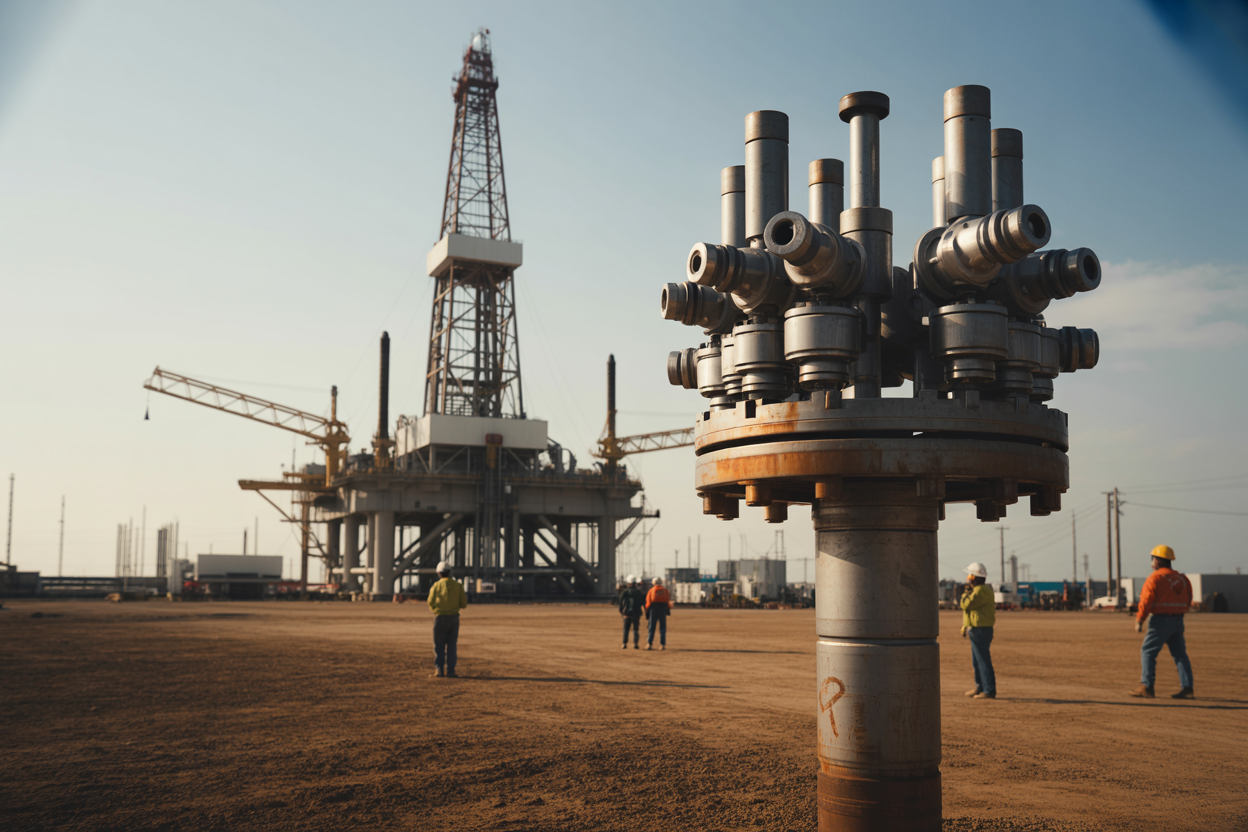
When drilling operations go wrong, your onshore blowout preventer stack stands between you and catastrophe. This critical piece of drilling equipment safety serves as your final barrier against uncontrolled well pressure that could endanger lives, damage equipment, and harm the environment.
This guide is designed for drilling engineers, rig supervisors, safety managers, and field technicians who need practical knowledge about onshore well control systems. Whether you’re new to the industry or looking to refresh your understanding of BOP stack components, you’ll find actionable insights here.
We’ll walk through the essential components that make your blowout preventer reliable and effective. You’ll also learn proven BOP stack installation techniques that maximize protection from day one. Finally, we’ll cover the maintenance protocols that keep your defense system ready when you need it most, because even the best equipment fails without proper care.
Your safety depends on understanding these systems inside and out. Let’s dive into what makes an onshore blowout preventer your most important piece of safety equipment.
Understanding Onshore Blowout Preventer Stacks and Their Critical Role
Essential components that prevent catastrophic well failures
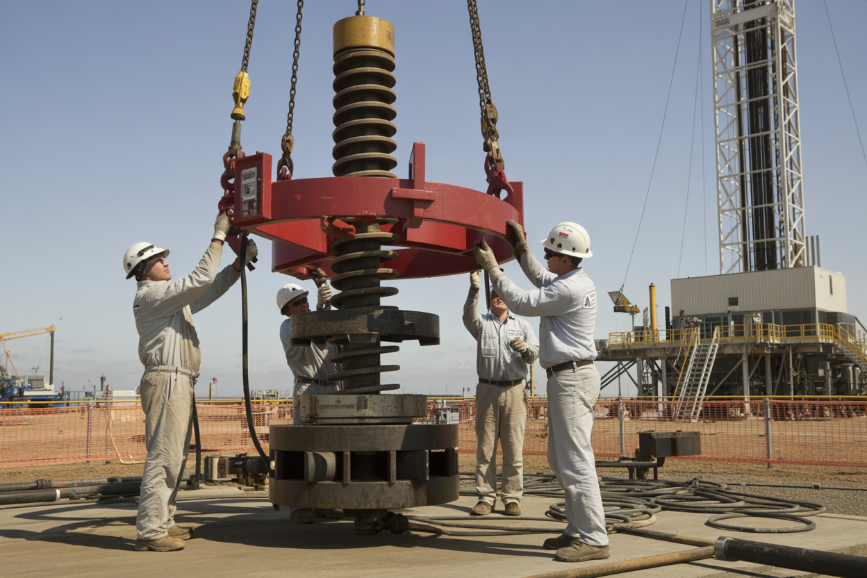
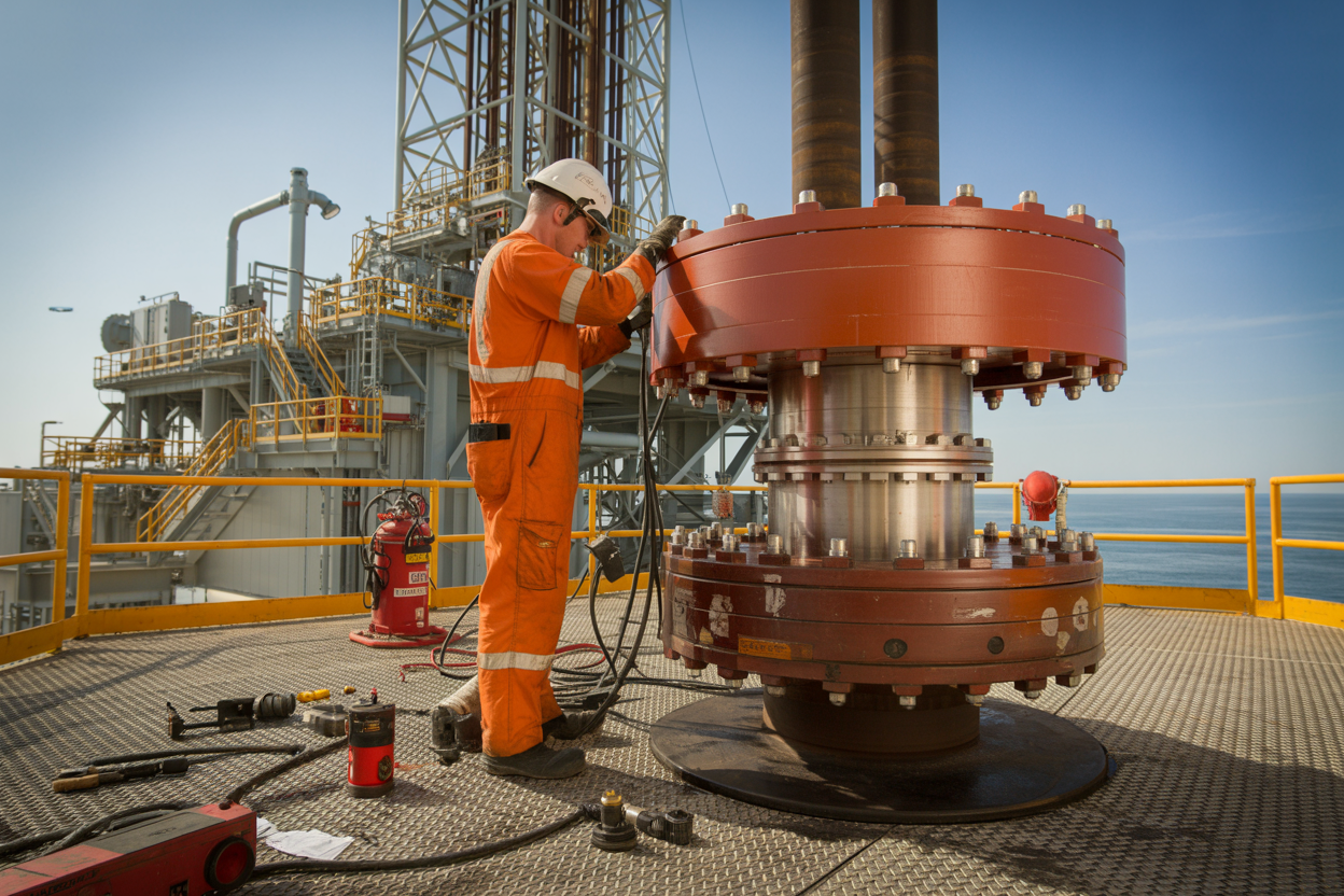
The onshore blowout preventer stack stands as your primary defense against well control emergencies, featuring several critical components working together. At its core, the ram preventer contains powerful hydraulic rams that can completely seal the wellbore around drill pipe or shut it off entirely when no pipe is present. These rams come in different configurations: pipe rams that close around specific drill pipe sizes, blind rams that seal an open hole, and shear rams capable of cutting through drill pipe if needed.
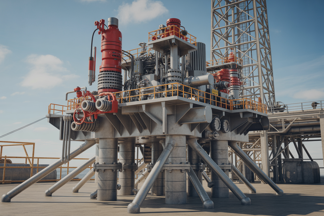
Below the ram preventer sits the annular preventer, which uses a flexible rubber packing element to create a seal around any shape or size of pipe. This versatility makes it invaluable during complex drilling operations where multiple pipe sizes might be in use.
The accumulator system provides the hydraulic pressure needed to operate these preventers instantly. Charged with nitrogen gas, accumulators store enough energy to close all preventers multiple times even if the primary power source fails. The control system, often called the driller’s panel, allows operators to activate any preventer combination with the push of a button.
Choke and kill lines complete the BOP stack components, providing controlled paths for managing well pressure during emergencies. These lines connect to specialized valves that allow crews to circulate drilling fluid while maintaining well control, giving them options beyond simply shutting in the well.
How BOPs serve as your final barrier against uncontrolled pressure release
When unexpected pressure surges threaten your drilling operation, the onshore blowout preventer becomes your last chance to prevent disaster. Think of it as an emergency brake system for your well – when everything else fails, the BOP stack must work flawlessly.
The moment downhole pressure exceeds your drilling fluid’s ability to control it, you’re facing a potential blowout. Hydrocarbons under extreme pressure will seek the path of least resistance, which is typically straight up through your wellbore. Without proper blowout preventer maintenance and operation, this scenario leads to uncontrolled releases that can ignite, causing fires, explosions, and environmental damage.
Your BOP stack stops this chain of events by creating an immediate mechanical seal. The rams close with tremendous force – often exceeding 1,000 psi of operating pressure – creating a barrier that can withstand pressures of 10,000 psi or more. Even if drill pipe is in the hole, pipe rams seal around it while allowing controlled circulation through choke lines.
The annular preventer adds another layer of protection, especially during connections or when running different pipe sizes. Its rubber element can squeeze shut around virtually any object in the wellbore, adapting to irregular shapes that rigid rams might not seal against perfectly.
Key differences between onshore and offshore BOP systems
Onshore drilling safety requirements differ significantly from offshore operations, leading to distinct BOP configurations. Land-based systems typically feature smaller, lighter preventers since they don’t face the extreme environmental conditions of marine drilling.
The most obvious difference lies in size and complexity. Offshore BOPs often include multiple ram preventers stacked vertically, sometimes reaching heights of 40 feet or more. Onshore installations usually require fewer preventers due to shorter drilling depths and lower pressure ratings.
| Feature | Onshore BOP | Offshore BOP |
|---|---|---|
| Typical Height | 15-25 feet | 35-50 feet |
| Ram Preventers | 2-3 units | 4-6 units |
| Operating Pressure | 2,000-10,000 psi | 5,000-15,000 psi |
| Control System | Surface mounted | Subsea pod system |
| Maintenance Access | Ground level | Requires rig equipment |
Onshore systems benefit from immediate access for maintenance and inspection. You can walk around the entire BOP stack, perform daily checks, and spot potential problems before they become critical. Offshore systems must be designed for remote operation and extended periods without hands-on maintenance.
The control systems also differ dramatically. Onshore drilling operations use surface-mounted control panels with direct hydraulic lines to the preventers. This setup provides instant response times and allows drillers to feel the equipment’s response. Offshore systems often rely on complex electronic controls and backup systems due to the distances involved.
Industry statistics showing BOP effectiveness in preventing disasters
Data from drilling safety organizations reveals that properly maintained onshore blowout preventer systems successfully contain over 98% of well control incidents. The American Petroleum Institute reports that BOP-related failures account for less than 2% of blowout incidents when equipment receives regular maintenance and testing.
Recent five-year industry data shows significant improvements in onshore well control:
- Blowout incidents decreased 65% since implementing enhanced BOP testing protocols
- Equipment failure rates dropped to 0.3% for systems following recommended maintenance schedules
- Response times improved to under 30 seconds for modern hydraulic systems
- Zero fatalities occurred in incidents where BOPs activated successfully
The International Association of Drilling Contractors tracks these metrics across thousands of wells annually. Their data consistently shows that BOP stack components perform most reliably when operators follow strict testing and maintenance protocols. Wells using preventers tested within the last 30 days show 40% fewer control issues compared to those with longer testing intervals.
Failure analysis reveals that human error causes more problems than equipment malfunction. Poor drilling safety procedures, inadequate crew training, and delayed response times contribute to 75% of incidents where BOPs fail to prevent blowouts. This reinforces why proper operational procedures matter as much as equipment quality.
Regional statistics show onshore drilling safety varies by location, with areas having stricter regulatory oversight reporting fewer incidents. States requiring daily BOP testing report 30% fewer well control problems than those with weekly testing requirements.
Core Components That Make Your BOP Stack Reliable
Ram Preventers That Seal Around Drill Pipe and Tubulars
Ram preventers form the backbone of any reliable onshore blowout preventer stack. These mechanical devices create a complete seal around drill pipe, casing, or other tubulars passing through the wellbore. Most BOP stack configurations include multiple ram preventers, each serving a specific sealing function.
Pipe rams seal around the external diameter of drill pipe or tubing. The rubber packing elements conform to the pipe’s outer surface, creating a pressure-tight seal while allowing the pipe to remain in the wellbore. These rams accommodate various pipe sizes, making them versatile for different drilling operations.
Blind rams provide complete wellbore closure when no pipe is present. The steel ram blocks meet in the center of the wellbore, creating a metal-to-metal seal that can withstand extreme pressures. Blind rams serve as the ultimate barrier when you need to shut in the well completely.
Shear rams represent the most powerful component in your BOP stack components arsenal. These rams can cut through drill pipe, wireline, or other downhole equipment while simultaneously sealing the wellbore. Variable bore rams accommodate multiple pipe sizes with a single set of ram blocks, reducing the need for frequent ram changes during drilling operations.
The hydraulic operating system provides the force necessary to close ram preventers rapidly. Accumulator bottles store pressurized hydraulic fluid, ensuring instant response even during power failures. Proper ram preventer selection depends on wellbore pressure ratings, pipe specifications, and operational requirements specific to your onshore drilling safety protocols.
Annular Preventers Providing Flexible Sealing Capabilities
Annular preventers bring unmatched versatility to onshore blowout preventer systems. Unlike ram preventers with fixed geometries, annular preventers feature a flexible rubber packing element that can seal around irregular shapes, multiple objects, or completely close an open hole.
The spherical or donut-shaped packing element squeezes inward when hydraulic pressure activates the closing unit. This flexible sealing action accommodates drill pipe, kelly bars, wireline, multiple tubulars, or even irregularly shaped objects that might be in the wellbore during an emergency.
Rotating capabilities set annular preventers apart from other BOP stack components. The packing element can maintain a seal while allowing controlled rotation of the drill string. This feature proves invaluable during well control operations where pipe manipulation becomes necessary while maintaining wellbore pressure control.
Modern annular preventers handle pressure differentials up to 10,000 psi or higher, depending on the manufacturer and model. The packing element design varies between manufacturers, but all focus on creating reliable seals across a wide range of pipe sizes and operating conditions.
Regular packing element inspection becomes critical for maintaining annular preventer reliability. The rubber elements wear over time and exposure to drilling fluids, hydrogen sulfide, and temperature extremes. Replacement intervals depend on operating conditions, but most operators follow manufacturer recommendations combined with visual inspections after each well.
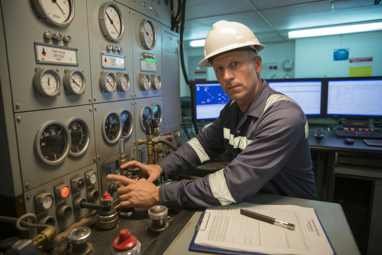
Control Systems Ensuring Rapid Response During Emergencies
Control systems represent the nervous system of your onshore blowout preventer stack, translating human decisions into immediate mechanical action. Modern BOP control systems combine hydraulic power with electronic monitoring to deliver split-second response times during critical well control situations.
Hydraulic accumulator systems provide the muscle behind BOP operations. Multiple accumulator bottles store pressurized hydraulic fluid at 3,000 psi or higher, ensuring sufficient energy reserves for multiple BOP functions without relying on pumps or external power. Accumulator capacity calculations must account for closing all BOP components plus reserve volume for extended operations.
Remote control panels position operators safely away from the wellhead while maintaining complete control over all BOP stack components. These panels feature individual controls for each ram preventer, annular preventer, and auxiliary functions like kill line valves or choke line valves. Emergency stop buttons provide immediate shutdown capabilities.
Electronic monitoring systems track hydraulic pressures, accumulator levels, and BOP component positions in real-time. Modern systems integrate with drilling automation platforms, providing continuous status updates and automated responses to preset conditions. Data logging capabilities support post-incident analysis and regulatory compliance requirements.
Backup control systems ensure redundancy during primary system failures. Manual backup controls, secondary hydraulic circuits, and independent power supplies maintain BOP functionality even when primary systems fail. Dead man switches automatically activate BOP closure if control system communication is lost, providing an additional safety layer for onshore drilling safety operations.
Testing protocols verify control system response times and functionality. Regular function tests exercise all BOP components while monitoring response times, pressures, and leak rates to ensure your blowout preventer maintenance program keeps systems ready for emergency activation.
Installation Best Practices That Maximize Protection
Proper stack configuration for your specific drilling conditions
Getting your BOP stack configuration right depends heavily on your drilling environment. Shallow formations with low pressure requirements might only need a basic stack with one set of rams, while deeper wells demand multiple ram preventers and additional safety barriers. Consider your maximum anticipated surface pressure when selecting component ratings – your stack should handle at least 1.5 times your expected working pressure.
Formation characteristics play a huge role in configuration decisions. Hard rock drilling calls for different ram configurations than soft sediment operations. Variable bore hole preventers work best in formations where hole stability issues might cause diameter variations. For high H2S environments, ensure all elastomers and sealing components meet sour gas service specifications.
Your drilling fluid type affects stack design too. Oil-based muds require different sealing materials compared to water-based systems. Some synthetic muds can degrade certain elastomer compounds over time, so verify compatibility before installation.
Critical testing procedures before deployment
Never skip the pressure testing phase – your crew’s safety depends on thorough verification. Start with a low-pressure test at 200-300 psi to check for obvious leaks, then gradually increase to full working pressure. Hold each pressure level for at least 10 minutes, watching for any pressure drops that signal seal problems.
Function testing comes next. Operate each ram and annular preventer through complete closing and opening cycles. Check closing times against manufacturer specifications – rams should close within 30-45 seconds under normal conditions. Test your accumulator system by cycling preventers with pumps shut down to verify stored pressure capacity.
Don’t forget the kill and choke line testing. These systems must handle full working pressure and maintain integrity during emergency operations. Test remote control functions from the driller’s console and backup control station. Verify all pressure gauges read accurately by comparing with a calibrated test gauge.
Run a complete system simulation that mimics an actual blowout scenario. This reveals potential issues that individual component tests might miss.
Positioning strategies that optimize emergency response times
Stack positioning directly impacts your response effectiveness during emergencies. Install your BOP stack as close to the wellhead as possible while maintaining safe working clearances. Every foot of distance between preventers and the hole adds response time during critical moments.
Arrange your accumulator bottles within 50 feet of the stack when possible. Longer control line runs create lag time and pressure losses that slow preventer activation. Position the accumulator manifold where operators can quickly access manual overrides if automatic systems fail.
Consider preventer stack orientation relative to prevailing winds. Blowouts often involve fire, and you want gas flow directed away from other equipment and personnel areas. Plan escape routes around your stack location – crews need clear paths to safety that don’t cross potential gas release zones.
Your choke and kill line routing affects response times too. Avoid sharp bends and unnecessary length. Route these lines to your choke manifold using the most direct path while maintaining proper support and protection from mechanical damage.
Integration with existing well control equipment
Modern onshore drilling operations require seamless integration between your BOP stack and existing control systems. Your accumulator capacity must support both the new stack and any existing preventers or safety systems. Calculate total fluid volume requirements for simultaneous operation of all preventers.
Control system compatibility becomes crucial when adding new equipment to established rigs. Verify that your existing control panels can handle additional preventer functions. Some older systems need control line upgrades to maintain proper pressure and response times across expanded equipment arrays.
Choke manifold integration requires careful planning. Your new BOP stack outlets must match existing manifold connections. Different manufacturers sometimes use incompatible fittings, requiring adapter flanges or complete manifold modifications. Plan these connections during the design phase rather than discovering incompatibilities during installation.
Emergency shutdown systems need coordination across all equipment. Your BOP stack emergency controls should integrate with rig safety systems, mud pump shutdowns, and rotary table locks. Test these integrated systems thoroughly – component integration often creates unexpected failure points that individual equipment tests won’t reveal.
Power requirements for integrated systems can exceed existing capacity. Calculate total hydraulic and electrical loads for your complete system, including backup power needs during primary system failures.
Maintenance Protocols That Keep Your Defense System Ready
Daily Inspection Routines That Prevent Equipment Failure
Checking your onshore blowout preventer every day isn’t just good practice—it’s what keeps your crew safe and your operation running smoothly. Start each shift by walking around the entire BOP stack installation and looking for obvious signs of trouble: hydraulic fluid leaks, damaged control lines, or corroded connections.
Your daily checklist should include testing all control functions. Cycle each ram through its full range of motion and verify that the annular preventer responds properly to commands. Check hydraulic accumulator pressure levels and top off fluids as needed. Pay special attention to the control pod connections and verify that all emergency shutdown systems are operational.
Don’t forget the smaller details that can cause big problems. Inspect seals, gaskets, and O-rings for wear or damage. Look for any unusual vibrations or noises during operation. These early warning signs often save you from costly downtime later.
Document everything you find, even if it seems minor. A small leak today could become a major failure tomorrow. Your BOP maintenance protocols depend on catching these issues before they escalate.
Scheduled Pressure Testing Requirements and Procedures
Blowout preventer testing follows strict schedules that you can’t ignore. Most operations require full BOP pressure tests every 14 days, but check your local regulations since requirements vary by location and well type.
Start with low-pressure tests before moving to full working pressure. Test each ram independently, then test the entire stack as a system. Hold pressure for the required duration—typically 5 to 10 minutes depending on your specifications. Any pressure drop indicates a potential problem that needs immediate attention.
| Test Type | Frequency | Test Pressure | Hold Time |
|---|---|---|---|
| Low Pressure | Every 7 days | 200-300 psi | 5 minutes |
| High Pressure | Every 14 days | Working pressure | 10 minutes |
| Function Test | Daily | Operating pressure | 2 minutes |
Your onshore well control procedures should include backup testing methods. If your primary test fails, have secondary verification procedures ready. Always test the backup control systems during your scheduled maintenance windows.
Component Replacement Schedules Based on Usage Patterns
Different components wear out at different rates depending on how hard you’re working your equipment. Rubber goods like packers and seals typically need replacement every 3-6 months in active drilling operations. Metal components last longer but still require regular evaluation.
Track your operating hours and cycles for each component. Pipe rams that see constant use need more frequent inspection than annular preventers that only activate during emergencies. Keep detailed records of when each part was installed and how many cycles it has completed.
Stock critical spare parts based on your usage patterns. If you’re drilling through abrasive formations, you’ll burn through ram blocks faster than normal. Sour gas operations are particularly hard on seals and require more frequent replacements.
Create a replacement schedule that accounts for both time and usage. A ram that sits idle for months might still need replacement due to age-related deterioration, while high-cycle components need replacement based on operational wear.
Documentation Systems That Ensure Compliance and Reliability
Your paperwork keeps you compliant and your equipment reliable. Create maintenance logs that capture every inspection, test, and repair. Include photos of any damage or wear patterns—these visual records help track component degradation over time.
Digital systems work better than paper for most operations. They make it easier to search historical data and identify trends. When a component fails, you can quickly review its maintenance history and identify potential causes.
Your drilling safety procedures require complete documentation trails. Regulators want to see proof that you’ve followed proper maintenance protocols. Missing documentation can shut down your operation, even if your equipment is in perfect condition.
Set up automated reminders for scheduled maintenance tasks. Nothing falls through the cracks when your system alerts you before deadlines approach. Include manufacturer recommendations, regulatory requirements, and your own operational standards in your scheduling system.
Emergency Repair Procedures for Field Situations
When your BOP stack fails during drilling operations, you need rapid response procedures that get you back online safely. Keep emergency repair kits on location with the most common failure items: seals, packing elements, and hydraulic fittings.
Train your crew on emergency shutdown procedures before you need them. Everyone should know how to safely shut down operations and isolate the failed component. Speed matters, but safety comes first—rushed repairs often make problems worse.
Establish clear decision trees for different failure scenarios. Some problems require immediate evacuation while others allow for on-site repairs. Your onshore drilling safety protocols should specify exactly who makes these decisions and what criteria they use.
Have backup equipment ready when possible. A spare control pod can keep you operational while you repair the primary system. Redundant hydraulic systems let you maintain well control even with partial equipment failures.
Keep emergency contact information for equipment manufacturers and specialized repair services. Some repairs require factory-trained technicians or specialized tools that you might not have on location.
Operational Procedures That Activate Your Last Line of Defense
Real-time monitoring systems that detect pressure anomalies
Modern drilling operations rely on sophisticated monitoring systems that track critical parameters around the clock. These systems constantly measure downhole pressure, mud flow rates, pit volumes, and gas concentrations to spot potential well control issues before they escalate. Smart sensors positioned throughout the drilling assembly feed data to control room operators who watch for pressure spikes, unexpected fluid returns, or sudden changes in drilling behavior.
The most effective monitoring setups combine multiple data streams into unified dashboards that highlight anomalies through color-coded alerts and automated warnings. When pressure readings jump outside normal parameters, these systems trigger immediate notifications to both the drilling crew and supervisory personnel. Advanced installations include predictive analytics that can identify subtle pressure trends indicating possible formation kicks or equipment failures.
Operators typically establish baseline pressure profiles for each well section, making it easier to spot deviations that signal trouble. Real-time data logging creates permanent records for post-drilling analysis and regulatory compliance. The key to successful monitoring lies in training crew members to interpret data quickly and respond appropriately when alerts sound.
Emergency response protocols for rapid BOP activation
Quick BOP activation can mean the difference between a controlled situation and a catastrophic blowout. Emergency protocols establish clear trigger points for activating different BOP functions based on well conditions and threat levels. Drilling crews practice specific response sequences that account for various scenarios, from minor pressure kicks to complete well control loss.
Primary response procedures typically follow a tiered approach starting with soft shut-in techniques using annular preventers before escalating to ram preventers if needed. Each crew member has designated responsibilities during emergency activation, eliminating confusion when seconds count. The driller maintains primary control over BOP functions while the toolpusher coordinates with the control room and additional support personnel.
Emergency checklists posted at key locations remind crews of proper activation sequences and safety considerations. These protocols include backup activation procedures using secondary control systems if primary controls fail. Regular emergency drills help crews maintain muscle memory for critical responses, while post-drill evaluations identify areas needing improvement. Successful emergency protocols also account for equipment limitations and weather conditions that might affect BOP performance.
Communication procedures between drilling crew and control room
Clear communication channels between field crews and control room personnel create the foundation for effective blowout prevention. Established radio protocols ensure important information reaches decision-makers without delay or confusion. Standard terminology eliminates misunderstandings about well conditions, equipment status, and required actions during high-stress situations.
Communication procedures define reporting requirements for routine operations and emergency conditions. Crew members know exactly when to contact supervisors, what information to provide, and which personnel need immediate notification. Backup communication systems remain ready when primary channels fail, including satellite phones and alternative radio frequencies.
Regular status updates keep control room operators informed about drilling progress, equipment performance, and any developing concerns. Emergency communication protocols bypass normal reporting chains to reach key decision-makers instantly when well control situations arise. Documentation requirements ensure all critical communications get recorded for later review and regulatory compliance.
Post-incident evaluation processes for continuous improvement
Every well control event, whether minor or major, provides valuable learning opportunities through systematic post-incident analysis. Evaluation teams review monitoring data, communication records, and crew responses to identify what worked well and what needs improvement. These assessments examine equipment performance, procedure effectiveness, and human factors that influenced the incident outcome.
Root cause analysis helps teams understand why problems occurred and how similar issues can be prevented in future operations. Evaluation processes gather input from all personnel involved, creating comprehensive pictures of incident timelines and contributing factors. Findings get documented in detailed reports that inform updates to drilling safety procedures, equipment specifications, and training programs.
Best practices from incident evaluations get shared across drilling operations to benefit other crews and locations. Follow-up actions ensure recommended improvements actually get implemented rather than simply filed away. Regular review of past incidents helps identify recurring patterns that might indicate systemic issues requiring broader organizational changes. The most successful evaluation programs create positive learning environments where crews feel comfortable reporting problems and near-misses without fear of punishment.
References and Resources
Industry Standards and Regulations
API Standard 16A provides the fundamental specifications for onshore blowout preventer design and manufacturing requirements. This standard covers everything from material specifications to pressure testing protocols that ensure your BOP stack components meet industry safety benchmarks. The API 16C standard complements this by establishing specific requirements for BOP control systems and actuating equipment.
IADC (International Association of Drilling Contractors) guidelines offer practical recommendations for BOP maintenance protocols and operational procedures. Their well control certification programs provide essential training frameworks for personnel working with onshore drilling safety systems.
The Bureau of Safety and Environmental Enforcement (BSEE) regulations, while primarily focused on offshore operations, contain valuable technical requirements that many onshore operators adopt as best practices for blowout preventer testing and maintenance.
Technical Documentation and Manuals
Cameron, Shaffer, and National Oilwell Varco publish comprehensive technical manuals for their BOP stack components. These manufacturer resources contain detailed installation procedures, maintenance schedules, and troubleshooting guides specific to each equipment model.
The Well Control Institute offers technical publications covering onshore well control scenarios and emergency response procedures. Their case study collections provide real-world examples of BOP system performance during actual well control events.
Training and Certification Resources
IWCF (International Well Control Forum) certification programs cover BOP stack installation and operational procedures for onshore drilling operations. Their Level 3 and Level 4 certifications specifically address surface BOP systems and drilling equipment safety protocols.
Local community colleges and technical schools often partner with drilling contractors to provide hands-on training programs focused on blowout preventer maintenance and testing procedures.
Professional Organizations
The Society of Petroleum Engineers (SPE) maintains extensive libraries of technical papers covering advances in BOP technology and onshore drilling safety innovations. Their annual conferences feature presentations on the latest developments in drilling equipment safety and well control techniques.

Blowout preventer stacks represent the most critical safety barrier standing between your crew and potential disaster. These sophisticated systems, with their pipe rams and multiple components working together, demand respect and proper handling at every stage of operation. The difference between a successful drilling project and a catastrophic event often comes down to how well you understand, install, and maintain your BOP stack.
Your safety protocols are only as strong as your weakest link, and that’s why every component matters. Regular maintenance checks, proper installation procedures, and well-trained operational teams create the foundation for reliable protection. Don’t wait for an emergency to test your system’s readiness – make BOP stack integrity a daily priority. When the unexpected happens, your last line of defense needs to work the first time flawlessly, every time.
Watch this video to summarize this article
Conclusion

Blowout preventer stacks stand as the most critical safety barrier in oil and gas drilling operations. When everything else goes wrong, these systems are what keep catastrophic blowouts from happening. We’ve covered the different types of BOP configurations, from simple surface units to complex deepwater stacks, and seen how each component plays a vital role in well control. The rams, annular preventers, and control systems work together like a well-rehearsed emergency team, ready to shut down dangerous pressure surges at a moment’s notice.
Regular testing and maintenance aren’t just industry requirements – they’re what make the difference between a system that works when needed and one that fails at the worst possible moment. The real-world case studies show us that proper BOP stack management has prevented countless disasters, while also highlighting what happens when these systems aren’t given the attention they deserve. If you’re working in drilling operations, make BOP stack integrity your top priority. Your crew’s safety and the environment depend on these systems working perfectly when seconds count.