


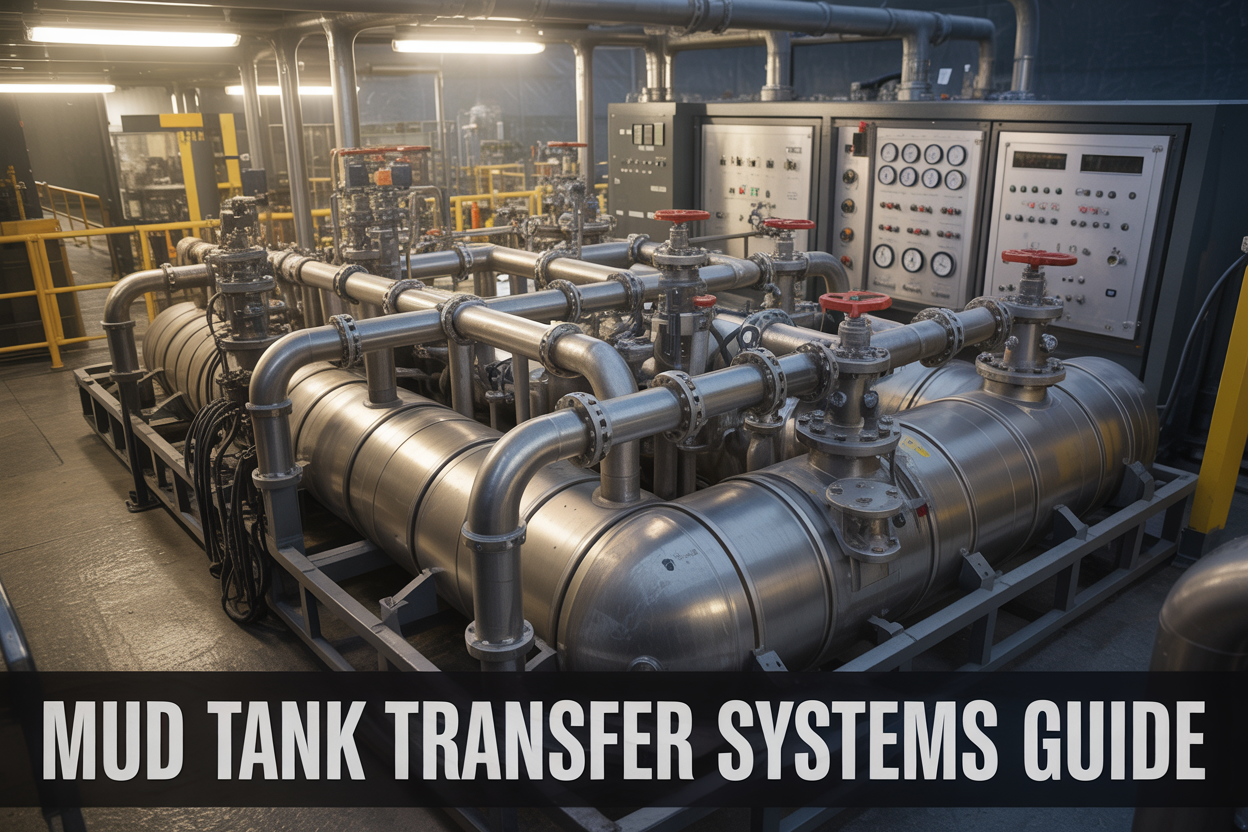
The Ultimate Guide to Rig Mud Tank Transfer Systems
If you work on a drilling rig or manage oilfield operations, you already know that keeping drilling fluid moving efficiently can make or break a job. Mud tank transfer systems are the backbone of any well-run rig floor operation — and when they fail, everything downstream feels it fast.
This guide is built for drilling engineers, rig supervisors, mud engineers, and anyone responsible for keeping a drilling fluid transfer system running at peak performance. Whether you’re setting up a new rig mud tank system from scratch or trying to squeeze more life out of aging equipment, you’ll find practical answers here.
Here’s what we’ll walk through:
- How mud tank transfer systems actually work — the core components, the flow paths, and why smart mud tank layout design directly affects your efficiency and safety on site
- Maintenance best practices and troubleshooting — the real-world steps that keep oilfield mud system components running longer and help you catch problems before they shut down operations
- Emerging tech changing the game — the advanced mud tank technology and automation tools that modern rigs are starting to adopt to cut downtime and improve fluid management
No fluff, no filler — just a straight look at what these systems do, how to run them well, and how to fix them when something goes sideways. Let’s get into it.
What Are Mud Tank Transfer Systems and Why They Matter
Core Purpose of Mud Tank Transfer Systems in Drilling Operations
At its heart, a mud tank transfer system is the circulatory system of a drilling rig. Just like your heart moves blood to where it needs to go, these systems move drilling fluid — commonly called mud — between storage tanks, active tanks, mixing hoppers, and the wellbore itself. Without a reliable transfer system, drilling operations would grind to a halt within hours.
Drilling mud serves several critical functions on a rig:
- Hydrostatic pressure control — keeping formation pressures in check and preventing blowouts
- Cuttings transport — lifting rock chips from the drill bit up to the surface
- Bit cooling and lubrication — reducing heat and friction at the drill string
- Wellbore stability — forming a filter cake that supports open-hole sections
- Lost circulation control — helping plug off thief zones that steal fluid
For the mud to do all of this effectively, it has to be in the right place, at the right volume, and at the right properties — at all times. That’s exactly what a mud tank transfer system makes possible.
The system manages the movement of mud through every phase of the drilling process: from initial mixing and treatment, through active circulation, to reserve storage and eventual pit-to-pit transfers during weight adjustments or emergency dilutions. On complex wells — deepwater, extended reach, or high-pressure/high-temperature (HPHT) — the demands on the transfer system become even more intense, requiring precision routing of different fluid weights and types without cross-contamination.
Think of it this way: a drilling crew might need to build a heavy kill mud in one tank while simultaneously circulating a lighter active system. The transfer system has to handle both simultaneously, cleanly, and safely. That kind of operational flexibility doesn’t happen by accident — it’s engineered into the system’s design from day one.
Key Components That Make Up a Complete Transfer System
A complete drilling fluid transfer system isn’t just a collection of pumps and pipes bolted together. It’s a carefully integrated network of hardware working in sync. Here’s a breakdown of the major components you’ll find on most modern rigs:
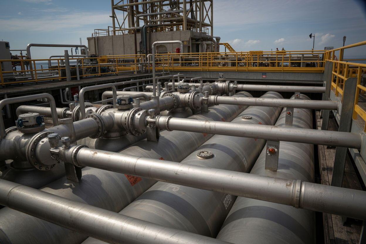
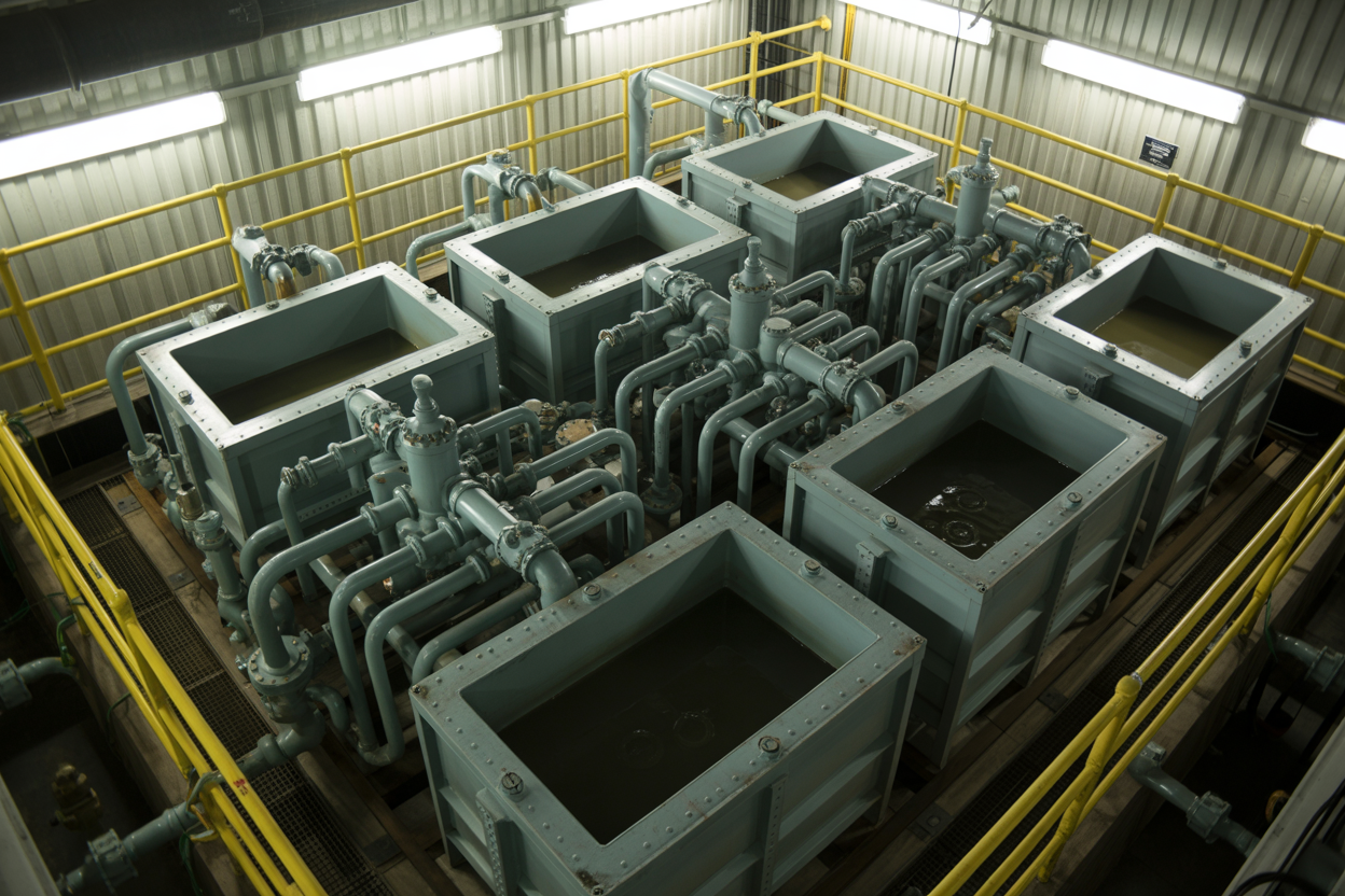
Mud Tanks (Pits)
These are the foundational storage vessels. Tanks are typically fabricated from steel and arranged in a linear or modular configuration on the rig floor footprint. Common tank types include:
| Tank Type | Primary Function |
|---|---|
| Active/Suction Tank | Feeds the mud pumps during active circulation |
| Reserve Tank | Stores backup mud volume for displacement or kills |
| Mixing Tank | Blending compartment for new mud preparation |
| Slug Tank | Holds heavy slug pills pumped before trips |
| Sand Trap | First receiver of returned mud from the shakers |
| Settling Tank | Allows solids to drop out before further processing |
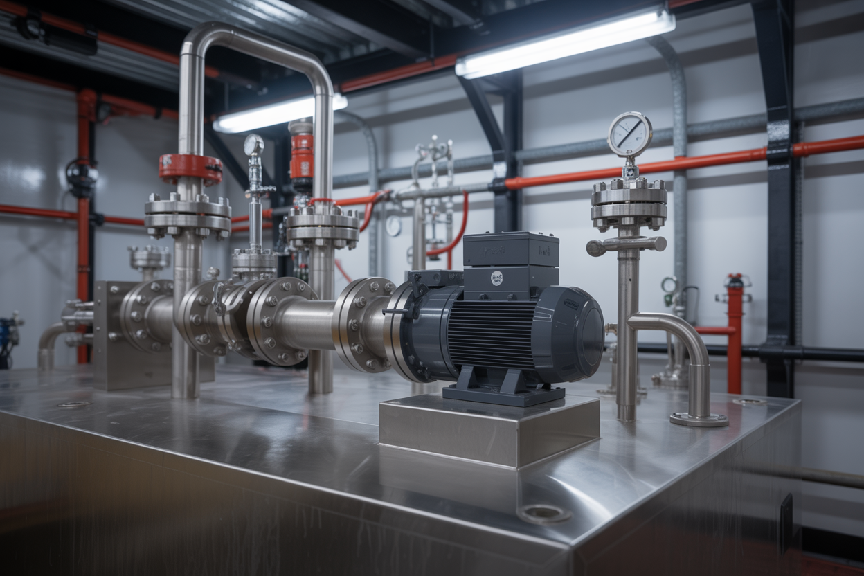
Transfer Pumps
Centrifugal pumps — not the rig’s main triplex or duplex mud pumps — do the heavy lifting for tank-to-tank transfers. These are typically 5″ x 6″ or 6″ x 8″ centrifugal units mounted at the tank bottom or on a dedicated pump skid. They’re sized to move large fluid volumes quickly, usually in the range of 500 to 1,500 GPM depending on rig size.
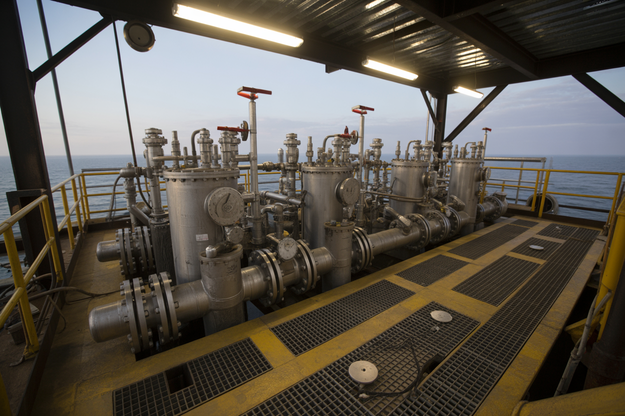
Suction and Discharge Manifolds
The manifold network is the nervous system of the transfer setup. A well-designed manifold allows any pump to pull from any tank and discharge to any other tank — giving the mud engineer maximum flexibility without having to physically swap hoses. Gate valves, butterfly valves, and plug valves are arranged at key connection points throughout the manifold.
Valves and Isolation Points
- Gate valves — reliable and durable for full open/full close applications
- Butterfly valves — compact and easier to operate for frequently cycled lines
- Plug valves — preferred in high-solids mud environments due to their wiper seal design
- Check valves — prevent backflow in transfer lines
Agitators and Mixers
Mud sitting still settles out. Agitators — driven by electric motors through right-angle gearboxes — keep the fluid in motion inside each tank compartment, preventing barite sag, maintaining uniform density, and keeping LCM (lost circulation material) suspended.
Hoppers and Mixing Jets
Chemical additions and weighting material (barite, calcium carbonate) enter the system through a mixing hopper. A high-velocity jet nozzle inside the hopper creates a venturi effect that draws powder into the mud stream without dusting or clumping.
Flowlines and Interconnecting Piping
The physical piping network — typically 4″ to 8″ schedule 40 or 80 steel pipe — connects every component in the system. On offshore rigs, this piping is permanently welded. On land rigs, a combination of hard piping and flexible connections is common to allow for skid repositioning.
How Transfer Systems Impact Overall Rig Efficiency and Safety
The quality and design of a mud tank transfer system shows up directly in two places: the morning report’s drilling performance numbers and the safety incident log. Here’s why both are heavily influenced by how well the system is built and operated.
Operational Efficiency
When transfer systems work smoothly, the mud engineer can respond fast. Need to pump a heavy kill pill? The slug tank is pre-positioned, and the transfer pump moves it to the suction tank in minutes. Need to dilute active mud weight to avoid differential sticking? Open a valve, run the transfer pump, done.
Poor transfer system design creates the opposite situation:
- Delays in fluid density adjustments during critical well control events
- Inability to move adequate volume fast enough during lost circulation response
- Cross-contamination between oil-based mud (OBM) and water-based mud (WBM) systems
- Excessive NPT (non-productive time) tied to manual hose rigging
On a day-rate rig, every hour of NPT costs thousands to hundreds of thousands of dollars. A poorly routed or undersized transfer system can silently bleed rig performance day after day.
Safety Implications
The mud tank area is one of the higher-risk zones on any rig. Consider the hazards:
- Fluid spills from leaking connections create slip hazards and environmental violations
- H₂S exposure — mud tanks can release toxic gas, especially when circulating out contaminated returns
- Mechanical hazards — rotating agitators, pump impellers, and pressurized lines require careful management
- Wellbore control risks — a misconfigured transfer valve at the wrong moment can route mud to the wrong place during a kick, worsening the situation
A properly designed rig mud tank system includes clear valve labeling, logical flow path sequencing, physical line segregation between different fluid types, and engineered spill containment. These aren’t extras — they’re baseline requirements for safe operations.
Beyond physical design, trained personnel who genuinely understand how the transfer system is configured are the single biggest safety asset. On complex rigs, valve manifold diagrams are posted at transfer pump stations, and critical transfer paths are reviewed during pre-tour meetings. That culture of deliberate awareness is what keeps minor transfer errors from becoming major incidents.
Long-Term Rig Performance
Rigs with well-maintained, thoughtfully designed drilling fluid transfer systems also see measurable benefits in mud cost management. Better tank routing means less dilution waste, more efficient solids control, and cleaner mud recycling. When you’re spending $500 to $2,000 per barrel on premium synthetic-based mud, the ability to conserve and recycle fluid through a properly configured transfer system pays off quickly on the bottom line.
Types of Mud Tank Transfer Systems Used on Modern Rigs
Gravity-Fed Transfer Systems and Their Best Use Cases
Gravity-fed transfer systems work on a beautifully simple principle — mud flows downhill from one tank to another without any mechanical help. When your tanks are arranged in a stepped or tiered configuration, you can move drilling fluid between compartments purely through elevation differences and strategically placed gate valves or dump valves.
These systems shine in specific scenarios:
- Weighting up operations where you need to blend heavy mud from a mixing tank into active pits without disturbing the entire system
- Overflow and equalization between adjacent tanks that are set at different heights
- Emergency transfer situations where pump power may not be available
- Degassing operations where treated mud gravity-drains back into the suction pit after passing through a degasser unit
The biggest advantage here is reliability. There are no moving parts to fail, no motor to burn out, and no impeller to clog. On smaller rigs or land-based operations where the tank layout allows for it, gravity feed can reduce equipment costs and maintenance headaches considerably.
The obvious limitation is that you need elevation differences to make it work. On offshore rigs or compact rig-up configurations where space is tight and all tanks sit at roughly the same level, gravity alone won’t cut it.
Best use cases at a glance:
| Scenario | Why Gravity Works Well |
|---|---|
| Overflow between suction and mixing tanks | Tanks are naturally tiered during construction |
| Degasser discharge back to suction pit | Degasser is typically mounted above the active tank |
| Emergency backup fluid movement | No electrical dependency |
| Small land rig operations | Simple layout supports elevation differences |
Pump-Driven Transfer Systems for High-Volume Operations
When you’re moving large volumes of drilling fluid quickly and across significant distances or elevation changes, pump-driven transfer systems are what the job demands. These systems use dedicated transfer pumps — separate from your main rig mud pumps — to push fluid through a network of piping, manifolds, and valves between tanks, storage reserves, and mixing areas.
Types of Pumps Commonly Used
Centrifugal pumps are by far the most common choice for mud tank transfer. They handle high flow rates well, are relatively easy to maintain, and deal reasonably well with the abrasive, variable-density fluids common in drilling operations. You’ll typically see them in sizes ranging from 5 to 100+ horsepower depending on rig scale.
Positive displacement pumps (like plunger or diaphragm pumps) come into play when you’re dealing with very high-viscosity fluids or need precise volumetric control during transfers. They’re more expensive and require more attention, but they deliver consistent output regardless of backpressure.
Submersible transfer pumps are sometimes deployed inside the tanks themselves, which reduces suction lift issues and simplifies piping runs. They’re particularly popular in high-volume reserve pit systems.
Key Components in a Pump-Driven System
A well-designed pump-driven drilling fluid transfer system includes:
- Transfer pumps (centrifugal or positive displacement)
- Suction manifolds with isolation valves at each tank
- Discharge manifolds that can route to multiple destinations
- Flowmeters for volume tracking during transfers
- Pressure gauges and relief valves for system protection
- Motor control centers (MCCs) or VFDs for operational control
- Strainer baskets upstream of pump suctions to protect impellers
Where Pump-Driven Systems Excel
| Application | Why Pump-Driven is the Right Call |
|---|---|
| Large offshore rig operations | Long pipe runs and multiple decks require positive head pressure |
| High-density mud transfers | Heavy fluids won’t gravity feed efficiently |
| Time-sensitive operations | Pump speed allows fast, controlled volume movement |
| Reserve pit to active pit transfers | Often involves significant elevation gain |
| Automated fluid management systems | Pumps integrate easily with flow control instrumentation |
One thing crews sometimes overlook is matching pump capacity to the actual transfer volume needed. Oversizing pumps causes unnecessary wear and energy waste, while undersizing creates bottlenecks during critical transfer windows — like when you’re actively weighting up ahead of a high-pressure zone.
Hybrid Transfer Configurations for Maximum Flexibility
The most capable rig mud tank systems today don’t rely on just one transfer method. Hybrid configurations combine gravity-fed pathways with pump-driven circuits, giving drilling crews the ability to move fluid in multiple ways depending on what the operation demands at any given moment.
A typical hybrid setup might look like this:
- The reserve tanks sit slightly elevated and gravity-feed into a mixing/weighting tank through large-bore dump valves
- From the mixing tank, centrifugal transfer pumps push weighted mud into the active suction pit
- The active pit has a gravity overflow line back to a secondary suction pit as a backup
- A dedicated transfer pump loop connects all tanks via a common manifold, allowing any-to-any tank transfers when needed
This kind of layout gives you several operational advantages:
- Redundancy — if a pump goes down, gravity pathways can keep fluid moving
- Speed options — pump transfers for fast, high-volume movement; gravity for slow, steady equalization
- Reduced pump wear — not every transfer requires a pump, so you extend equipment life
- Better mixing control — gravity additions can be blended gently while pumps handle bulk volume movement
Hybrid System Design Considerations
Getting the most out of a hybrid configuration requires some careful planning upfront:
- Valve placement matters enormously — every junction point needs proper isolation valves so you can select pathways without cross-contaminating tank contents
- Pipe sizing needs to match both modes — gravity flow requires larger bore piping than pump-driven flow at the same volume
- Check valves should be installed on all gravity lines that connect to pump circuits to prevent backflow when pumps are running
- Clear labeling and flow diagrams posted at the manifold make it far easier for crews to execute correct valve lineups during shift changes or emergencies
Choosing the Right System Type for Your Rig Setup
Picking the right mud tank transfer system comes down to honestly assessing what your rig actually needs — not just what looks impressive on a spec sheet. Here are the main factors that should guide your decision:
Rig Type and Physical Layout
Offshore rigs — jackups, semis, and drillships — almost always need pump-driven systems because of multi-deck layouts and long horizontal pipe runs. Land rigs have more flexibility and can lean heavier on gravity-fed configurations if the tank arrangement supports it.
Mud Volume and Flow Rate Requirements
Look at your planned mud system volume and figure out your worst-case transfer scenario. If you’re running 2,000 barrels of active fluid and need to fully swap your suction tank in under 30 minutes, gravity isn’t going to get you there — you need pumps sized for that flow rate.
Fluid Properties
The heavier and more viscous your mud system, the harder gravity has to work. Water-based muds with weights up to around 12 ppg flow reasonably well under gravity on a good elevation difference. Synthetic-based or oil-based muds at 16+ ppg? You’re almost always going to want pump assistance.
Operational Complexity
If your crew is small or has high turnover, a simpler system with fewer transfer modes is often more practical than a highly flexible hybrid system that requires a detailed understanding to operate safely. The best mud pump transfer system for your rig is one your team can operate correctly every time, not just the most technically capable one.
Budget and Maintenance Capacity
| System Type | Capital Cost | Maintenance Requirements | Flexibility |
|---|---|---|---|
| Gravity-Fed Only | Low | Very Low | Limited |
| Pump-Driven Only | Medium-High | Medium-High | High |
| Hybrid Configuration | High | Medium | Very High |
A few practical questions worth asking before finalizing your choice:
- Do you have enough elevation difference to make gravity transfer meaningful?
- What’s your rig’s electrical and mechanical maintenance capability?
- How often will you need to reconfigure your mud system for different well programs?
- Are you operating in a regulatory environment that requires specific fluid management documentation (which may favor metered pump-driven systems)?
Answering these honestly will steer you toward the right oilfield mud system components and configuration for your specific operation — without overcomplicating what might be a straightforward setup.
Essential Equipment and Hardware for Optimal Performance
Selecting the Right Pumps for Reliable Mud Transfer
The pump is the heart of any mud tank transfer system, and picking the wrong one will cost you — in downtime, repairs, and headaches you really don’t need on a busy rig. Getting this decision right means understanding what your system actually demands before you start comparing specs.
Centrifugal vs. Positive Displacement Pumps
These are your two main options, and they serve very different purposes:
| Pump Type | Best Used For | Key Advantage | Limitation |
|---|---|---|---|
| Centrifugal | High-volume transfer between tanks | High flow rates, lower cost | Loses efficiency with thick muds |
| Positive Displacement (Triplex/Duplex) | Viscous or weighted mud transfer | Handles high-density fluids well | Lower flow rates, higher maintenance |
| Submersible | Pit cleanout, emergency transfer | Easy deployment, compact | Not suited for continuous operation |
| Screw Pump | Transfers with high solids content | Gentle on mud properties | More expensive upfront |
For most rig mud tank systems, centrifugal pumps handle the bulk of routine transfer work — moving fluid from the suction pit to the active system, circulating through the solids control equipment, and feeding the main mud pumps. They’re efficient, relatively easy to maintain, and widely available in oilfield-rated configurations.
When you’re moving weighted or high-viscosity drilling mud, a positive displacement pump gives you the pushing power centrifugals simply can’t deliver. The trade-off is more moving parts and a tighter maintenance schedule.
What to Look for When Sizing a Transfer Pump
- Flow rate requirements: Match pump output to your peak transfer demand, not just average flow. Running a pump constantly at its upper limit shortens its life fast.
- Head pressure: Account for elevation changes, pipe length, bends, and any backpressure from equipment downstream.
- Fluid density: A pump rated for water-based mud at 9 ppg needs to be re-evaluated when you’re running 16 ppg weighted fluid.
- Solids tolerance: If your mud carries a significant solids load, choose impeller designs built for abrasion resistance — open or semi-open impellers typically handle this better than closed styles.
- Seal type: Mechanical seals work well in clean conditions, but on a rig dealing with abrasive solids and temperature swings, packing seals are often more forgiving and easier to field-service.
Always build in some extra capacity. A pump running at 70–80% of its rated output will outlast one running at 95% every single time.
Valves, Manifolds, and Flow Control Components That Prevent Costly Failures
Pumps get most of the attention, but valves and manifolds are where your drilling fluid transfer system either comes together or falls apart. A poorly spec’d valve in the wrong location can take down your entire system faster than a pump failure ever would.
The Role of Manifolds in Mud Tank Transfer
A transfer manifold ties your entire mud system together — connecting tanks, pumps, and processing equipment so fluid can be routed wherever it needs to go with a minimum of hard plumbing changes. A well-designed manifold gives operators flexibility to:
- Bypass a piece of equipment without shutting down circulation
- Isolate individual tanks for cleaning or inspection
- Switch fluid sources quickly when conditions change
- Route returns to different pits during kick response
The manifold layout needs to be thought through during the design phase (covered more in Section 4), but the component selection matters just as much as the layout itself.
Valve Types and Where They Belong
Not all valves are equal, and mixing them up is a recipe for either a stuck-open disaster or a valve that wears out in weeks. Here’s a practical breakdown:
| Valve Type | Typical Application | Why It Works There |
|---|---|---|
| Gate Valve | Main isolation duties | Full-bore opening, low pressure drop |
| Plug Valve | High-cycle switching points on manifolds | Fast quarter-turn operation, handles abrasive slurries |
| Butterfly Valve | Large-diameter, low-pressure applications | Lightweight, compact, easy to actuate |
| Check Valve | Pump discharge lines | Prevents backflow when pump stops |
| Ball Valve | Instrumentation and sample ports | Tight shutoff, easy to operate |
| Knife Gate Valve | Slurry lines with heavy solids | Cuts through settled solids on closure |
For the harsh, abrasive conditions typical in drilling fluid transfer, plug valves and knife gate valves tend to hold up the best in high-wear locations. Gate valves are workhorses for isolation but don’t try to throttle flow with them — they’ll erode the seat quickly and start leaking.
Actuated vs. Manual Valves
Manually operated valves are fine for positions that don’t need frequent changes. But for any valve that gets cycled regularly — or one that needs to snap shut in an emergency — pneumatic or hydraulic actuation is worth the investment. Actuated valves:
- Reduce operator exposure to hazardous areas during emergency shutdowns
- Enable remote control from a driller’s console or automated control system
- Respond faster than a person can manually operate a handwheel under pressure
- Support automated sequencing when paired with a PLC-based control system
Position indicators are non-negotiable on actuated valves. You need to know with certainty whether a valve is open, closed, or stuck mid-travel.
Piping, Flanges, and Connection Hardware
The piping connecting your oilfield mud system components deserves the same attention as the valves themselves:
- Material selection: Carbon steel works for most applications, but stainless steel or lined pipe becomes necessary when dealing with corrosive fluids or saltwater-based muds.
- Pipe sizing: Velocity matters. Mud moving through transfer lines at over 8–10 ft/sec causes accelerated erosion, especially at elbows and tees. Size your pipe to keep velocities reasonable.
- Elbow design: Long-radius elbows (1.5D or 3D radius) cut erosion dramatically compared to standard short-radius fittings.
- Flange ratings: Make sure flange pressure ratings exceed your maximum expected system pressure with a comfortable safety margin. Flanges are often the weak link when system pressure spikes during a blockage or valve slam.
Sensors and Monitoring Instruments for Real-Time Transfer Visibility
Running a mud tank transfer system without good instrumentation is like driving at night with no headlights. You can do it for a while, but eventually something surprises you. Real-time monitoring gives your team the information they need to catch problems early, optimize transfers, and respond quickly when something goes wrong.
Tank Level Monitoring
Knowing exactly how much fluid is in each tank at any given moment is the foundation of effective mud management. Options range from simple mechanical floats to sophisticated ultrasonic and radar level transmitters:
- Ultrasonic level sensors: Non-contact, easy to install, and work well in most mud tank environments. They can struggle with heavy foam or steam on the fluid surface, but are reliable in most normal conditions.
- Radar level transmitters: More expensive but handle foam, vapor, and surface turbulence much better than ultrasonic devices. Good choice for active mixing compartments.
- Float and tape gauges: Low-tech and cheap but limited to point-in-time readings and require manual checking. Suitable as backup instruments.
- Pressure-based level transmitters: Mount at the tank bottom, infer level from hydrostatic pressure. Work well but need periodic recalibration when fluid density changes significantly.
For modern rig mud tank systems, you want continuous, real-time level data feeding into your monitoring system — not someone walking the pits with a measuring tape every hour.
Flow Measurement in Transfer Lines
Monitoring flow rates in your transfer lines tells you whether your pumps are performing as expected and helps detect problems like blocked lines, worn impellers, or unintended bypasses. The most practical options for drilling fluid transfer systems include:
| Instrument Type | Working Principle | Suitability for Mud Service |
|---|---|---|
| Magnetic Flowmeter | Measures electromagnetic induction in conductive fluid | Excellent — handles solids and viscous fluid well |
| Coriolis Flowmeter | Measures mass flow via vibration frequency | Very accurate, but expensive and sensitive to entrained gas |
| Ultrasonic Flowmeter | Clamp-on or inline acoustic measurement | Good for clean fluid, less reliable with high solids |
| Differential Pressure (Orifice Plate) | Pressure drop across restriction | Low cost, but wears quickly in abrasive service |
Magnetic flowmeters are the industry standard for mud service. They have no moving parts, offer full-bore measurement with no pressure drop, and handle the abrasive, conductive nature of drilling mud without degrading quickly.
Pump Performance Monitoring
Beyond just knowing flow rate, monitoring your transfer pumps directly helps catch wear and efficiency losses before they become outright failures:
- Discharge pressure gauges: Basic and essential. Abnormal pressure readings are often your first warning that something has changed — a blocked line, a worn impeller, or a developing valve problem.
- Current/power monitoring: Tracking motor amperage lets you catch bearing wear, cavitation, and impeller damage early. A pump pulling more amps than usual at the same flow rate is telling you something.
- Vibration sensors: Mounted on pump bearings, these catch imbalance, misalignment, and early bearing failure. More common on critical pumps but increasingly affordable across the board.
- Temperature sensors: Overheating bearings or mechanical seals are a common pre-failure indicator. A simple PT100 or thermocouple on bearing housing temperatures gives you an early warning system at minimal cost.
Integration and Alarming
Individual sensors only do so much if the data just sits there. Connecting your instrumentation to a centralized SCADA system or rig monitoring platform ties everything together:
- Set high and low level alarms on tanks to prevent overflow or pump dry-running
- Configure flow deviation alarms that flag when actual flow drops significantly below setpoint
- Log all transfer operations automatically for post-job analysis and regulatory compliance
- Feed data to the driller’s console so the crew has visibility without having to physically inspect the system
The goal is a system where your team knows what’s happening across the entire drilling mud transfer equipment package at a glance — and gets alerted immediately when something steps outside of normal operating boundaries.
Designing an Efficient Mud Tank Transfer Layout
Optimizing Tank Positioning to Minimize Transfer Distance and Energy Use
Tank positioning is one of those decisions that looks simple on paper but has a massive ripple effect on everything else in your mud system. Get it right, and you shave energy costs, reduce pump wear, and keep fluid moving where it needs to go without fighting gravity or geometry. Get it wrong, and you’re stuck with sluggish transfers, overworked pumps, and a layout that frustrates your crew on every shift.
The core principle here is straightforward: shorter transfer distances mean less friction loss, less energy consumption, and faster response times. When laying out your mud tank transfer system, position active pits — your suction tanks and mixing tanks — as close to the rig floor and mud pumps as physically possible. Reserve your reserve and storage tanks for the outer edges of the layout, since those see less frequent movement.
Key Positioning Principles to Follow
- Flow direction should be logical and linear. Mud should move from reserve storage → trip tanks → suction pits → mud pumps in a progression that minimizes backtracking through the system.
- Elevation matters. Where possible, position feed tanks slightly higher than receiving tanks to leverage gravity assist and reduce pump load on routine transfers.
- Group tanks by function. Keep active circulation tanks together, desilter and desander pits in their logical processing sequence, and waste/trip tanks in accessible but non-obstructive positions.
- Account for rig skid layout early. Modular rigs present unique constraints — plan tank positioning before the rig is mobilized, not after, because retrofitting a poor layout is expensive and time-consuming.
A common oversight is treating tank positioning as a space management problem rather than a fluid dynamics problem. Every additional 10 feet of horizontal pipe run adds friction loss. Every unnecessary elbow or tee fitting compounds that loss. Map your flow paths on paper before a single piece of equipment is placed, and you’ll save yourself a headache that would otherwise last the entire well campaign.
Sizing Pipelines and Flow Rates to Match Drilling Demands
Undersized lines choke your system. Oversized lines waste money and create low-velocity zones where solids settle and clog. Finding the right pipe diameter for your mud tank transfer system is about matching your system’s physical capacity to the actual demands of the well you’re drilling.
Start with your expected circulation rate. Most drilling operations run anywhere from 300 to 1,200+ gallons per minute (GPM) depending on hole size, depth, and mud weight. Your transfer lines need to handle peak demand — not just average demand — without causing excessive pressure drop.
Pipeline Sizing Quick Reference
| Transfer Type | Typical Flow Rate | Recommended Line Size | Max Velocity Target |
|---|---|---|---|
| Active Circulation (Suction) | 500–1,200 GPM | 6–8 inch | 5–8 ft/sec |
| Tank-to-Tank Transfer | 100–400 GPM | 4–6 inch | 4–6 ft/sec |
| Mixing/Hopper Lines | 50–150 GPM | 3–4 inch | 3–5 ft/sec |
| Trip/Reserve Transfers | 50–200 GPM | 4 inch | 4–5 ft/sec |
Keep fluid velocity within a practical window. Too slow (under 3 ft/sec for weighted muds), and solids drop out and build up in low spots. Too fast (over 8–10 ft/sec), and you’re accelerating erosion of pipe walls, elbows, and valve seats — especially when running abrasive weighted muds with barite or hematite.
Flow Rate Matching Checklist
- Calculate your maximum anticipated circulation rate and add a 20–25% buffer for surge demand scenarios.
- Size your suction lines one size larger than you think you need — suction-side pressure drop is where cavitation problems begin at the mud pump.
- Use long-radius elbows (3D or 5D radius) instead of standard 90° elbows wherever possible. The pressure drop difference on high-flow weighted mud lines is significant.
- Account for mud weight in your calculations. A 14 lb/gal mud behaves very differently from 9 lb/gal water-based mud in terms of friction loss and pump demand.
Don’t rely on rules of thumb alone. Run actual hydraulic calculations for your specific mud weights, flow rates, and pipe run lengths before finalizing your design. Drilling fluid transfer system engineering software can do this quickly, and it’s worth the time investment before you’re stuck with a system that can’t keep up at critical moments.
Building Redundancy Into Your System to Avoid Costly Downtime
Redundancy in a mud tank transfer system isn’t gold-plating — it’s insurance. On a drilling rig, downtime is measured in thousands of dollars per hour. A single pump failure or a blocked transfer line that takes your active system offline can result in a well control event, a stuck pipe, or simply a very expensive wait while someone scrambles to find a solution.
The goal isn’t to duplicate everything (that’s not practical or economical). The goal is to identify the single points of failure in your layout and build a bypass, backup, or alternative path around each one.
Where to Build Redundancy
Transfer Pumps
- Always have at least one standby centrifugal pump for each critical transfer duty — active suction, mixing, and trip tank transfer.
- Cross-connect pump suction and discharge headers so that any pump can draw from any tank and discharge to any destination in a pinch.
- Use isolation valves (gate or plug valves) at every pump inlet and outlet so a failed pump can be isolated without shutting down the entire header.
Piping Headers and Valves
- Design your main transfer header with bypass loops so that a section of blocked or leaking pipe can be isolated while transfers continue through an alternate path.
- Install tie-in points (flanged spools or unions) at regular intervals so temporary hose bypasses can be rigged up quickly.
- Every critical line should have manual isolation capability, even if normal operation is automated.
Tank Compartmentalization
- Never rely on a single active pit. A two-compartment or three-compartment active system lets you isolate one compartment for cleaning or repair without interrupting circulation.
- Trip tanks should always have independent pump capability — don’t route them through the same pump that handles active circulation.
Electrical and Control Systems
- Backup power supply for pump motor starters and control panels at minimum.
- Manual override capability for all automated valves — you want your crew to be able to run the system manually if the automation goes dark.
Redundancy Planning Matrix
| System Component | Primary | Backup Option | Isolation Method |
|---|---|---|---|
| Active Transfer Pump | Centrifugal pump A | Centrifugal pump B (standby) | Inlet/outlet block valves |
| Suction Header | Primary 6″ header | Secondary 4″ bypass | Manual gate valves |
| Active Pit | Compartment 1 | Compartment 2 | Bulkhead valve |
| Power Supply | Main rig power | Diesel generator backup | Automatic transfer switch |
| Valve Control | Automated actuators | Manual handwheel override | Direct mechanical |
Plan for your worst-case scenario during the design phase — not during a midnight emergency on tour.
Compliance and Safety Considerations in System Design
A well-designed mud tank layout has to meet more than just operational performance targets. Regulatory requirements, environmental standards, and rig safety codes all shape what you can and can’t do when designing a drilling fluid transfer system.
Regulatory Frameworks to Know
Depending on your operating region, your mud tank transfer system design may be subject to:
- API RP 13C and API RP 13J — Standards for drilling fluids, solids control equipment, and associated systems.
- OSHA 29 CFR 1910 and 1926 — Occupational safety requirements for confined spaces, hazardous materials handling, and equipment guarding relevant to mud tank areas.
- EPA and local environmental regulations — Particularly around secondary containment for drilling fluid storage, spill prevention (SPCC Plans), and waste fluid handling.
- IADC Well Control Standards — Relevant to trip tank design, kick detection requirements, and pit volume totalizer integration.
- Offshore-specific regulations — BSEE (Bureau of Safety and Environmental Enforcement) in the US, NOPSEMA in Australia, and equivalent bodies in other jurisdictions have specific requirements for offshore mud system design.
Safety Design Non-Negotiables
Secondary Containment
All mud tanks and transfer lines should be located within bermed containment areas with capacity to hold 110% of the largest tank volume — this is standard for SPCC compliance and good engineering practice regardless.
Personnel Safety Zones
- Keep high-traffic walkways clear of main transfer lines wherever possible. Lines do fail, and a high-pressure mud leak in a walkway is a serious injury risk.
- Guarding or caging on rotating pump components — impellers, couplings, belt drives — is non-negotiable.
- Non-slip grating on all mud tank walkways and around pump areas.
Pressure Relief and Overpressure Protection
- Centrifugal pumps used for transfer don’t typically require pressure relief valves since they’re non-positive-displacement, but any system using trip pumps or positive-displacement transfer pumps must have proper pressure relief.
- Closed transfer systems (pressurized tanks or sealed headers) need pressure/vacuum relief rated for their maximum operating pressure.
Bonding and Grounding
Particularly relevant when handling oil-based muds or synthetic-based muds. Static electricity buildup in transfer lines is a real ignition hazard. Bond all tank sections, pump housings, and piping to a common ground.
Signage and Labeling
Every valve, every line, every pump should be clearly labeled with its function, flow direction, and any relevant operating limits. Color-coding your pipeline system (by function or content) dramatically reduces the chance of human error during transfers.
Common Design Mistakes That Reduce Transfer Efficiency
Even experienced drilling engineers make layout decisions that seem fine in isolation but create serious operational problems once the system is running. Here are the mistakes that show up most often — and what they actually cost you.
Mistake 1: Not Accounting for Mud Weight Variation
Designing a rig mud tank system for a 10 lb/gal water-based mud and then running 16 lb/gal weighted mud is a pump killer. Friction losses scale with fluid density, and your system hydraulics change dramatically with heavy muds. Always design to your heaviest anticipated mud weight — and if you don’t know that yet, design conservatively.
Mistake 2: Too Many Sharp Turns and Fittings
Every standard 90° elbow in a 4-inch line handling heavy mud creates the equivalent pressure drop of several feet of additional straight pipe. On a layout with a dozen unnecessary elbows between tanks, you’re essentially adding hundreds of feet to your effective pipe length. Use long-radius elbows, design linear flow paths, and avoid gratuitous directional changes.
Mistake 3: Valves in the Wrong Locations
A common one: isolation valves placed on the discharge side of a pump only, with no suction isolation. When that pump needs to come offline, you can’t isolate it cleanly without draining sections of piping.
Mistake 4: Undersizing the Suction Side
Engineers often focus on discharge line sizing and neglect the suction side, which is actually more critical. A marginally undersized suction line causes the pump to cavitate — a problem that destroys impellers, reduces flow rate, and creates noise and vibration problems. The suction line should always be sized a step larger than the discharge line for the same pump.
Mistake 5: No Low-Point Drains
Transfer lines that run horizontally with no low-point drain connections are a maintenance nightmare. When the system needs to be cleared or flushed, you have nowhere to drain trapped fluid. Add drain valves at every natural low point in the layout — it takes minimal cost at the design stage and saves hours of work later.
Mistake 6: Ignoring Thermal Expansion
On facilities in regions with significant temperature swings — Arctic operations, desert environments, offshore platforms exposed to sun and spray — thermal expansion of long steel pipeline runs can cause stress at fixed connection points. Expansion loops or flexible connectors at appropriate intervals prevent cracking at welds and flanges over time.
Mistake 7: Single-Path Designs With No Bypass Options
If your mud tank layout only has one way to get fluid from point A to point B, any blockage, valve failure, or pump issue shuts down that path entirely. Cross-headers, tie-points, and flexible bypass connections aren’t overkill — they’re what keep you operational when something goes wrong at 2 AM on a critical section of hole.
Design Mistake Summary
| Mistake | Primary Impact | Prevention |
|---|---|---|
| Wrong mud weight assumption | Pump overload, cavitation | Design for maximum expected mud weight |
| Excessive fittings/elbows | High friction loss, poor flow | Use long-radius bends, linear layouts |
| Missing suction isolation | Poor maintenance access | Valve both sides of every pump |
| Undersized suction lines | Pump cavitation | Size suction one diameter larger than discharge |
| No low-point drains | Maintenance difficulty | Add drains at all low points during design |
| No thermal expansion allowance | Pipe stress, weld cracking | Use expansion loops or flex connectors |
| Single-path design | Zero redundancy | Build bypass capability at critical points |
Operating Mud Tank Transfer Systems Safely and Effectively

Step-by-Step Procedures for Safe Transfer Operations
Running a mud tank transfer system safely comes down to doing things in the right order, every single time. Skipping steps or rushing through procedures is how spills happen, equipment gets damaged, and people get hurt. Here’s how experienced rig crews approach transfer operations from start to finish.
Pre-Transfer Checklist
Before any fluid moves through the system, work through these checks:
- Verify tank levels — Confirm the destination tank has enough headroom to accept the volume being transferred without risking overflow.
- Inspect valve positions — Every valve in the transfer line should be in its correct position. Walk the line physically if needed; don’t just assume.
- Check pump condition — Review the mud pump transfer system for any signs of leaking seals, unusual vibration, or pressure anomalies from the previous shift.
- Confirm suction and discharge connections — Make sure the correct suction and discharge lines are open and all bypass valves are closed.
- Brief the crew — Everyone involved in the operation should know their role, the expected transfer volume, and the shutdown signal.
Transfer Execution
Once the pre-transfer checks are complete:
- Start the transfer pump slowly — Ramp up to operating speed gradually. Hard starts put unnecessary stress on pump seals and connections.
- Open suction valve first — Always open suction before engaging the pump or opening the discharge. This prevents cavitation and pressure spikes.
- Monitor flow rate — Use flow meters or pit level indicators to track how quickly fluid is moving. A sudden drop in flow rate can signal a blocked line or failing pump.
- Maintain two-person oversight — One person should manage the pump controls while another watches the receiving tank. Communication between them should be constant.
- Document the transfer — Log start time, volumes transferred, fluid weight, and any anomalies. This data is critical for troubleshooting and regulatory compliance.
Post-Transfer Procedures
- Close valves in the reverse order they were opened.
- Flush transfer lines if switching between different mud weights or fluid types.
- Secure the pump and record final pit volumes on the drilling fluid transfer system log.
- Inspect connections and fittings for any weeping or dripping before leaving the area.
Monitoring Fluid Levels and Preventing Overflow Hazards
Overflow events on a rig are messy, costly, and potentially dangerous. Drilling mud spilling onto grating or into the substructure creates slip hazards, contaminates other systems, and can trigger environmental reporting requirements. Keeping a close eye on fluid levels during transfer operations is non-negotiable.
Active Monitoring Tools
Modern rig mud tank systems are equipped with multiple layers of level monitoring:
| Monitoring Method | How It Works | Best Use Case |
|---|---|---|
| Float-type level sensors | Mechanical float triggers an alarm at a set level | Simple, low-cost backup system |
| Ultrasonic level sensors | Sound waves measure fluid surface distance | Works well with aggressive muds |
| Pressure transducers | Measures hydrostatic head to calculate volume | High accuracy in sealed or agitated tanks |
| Visual sight gauges | Direct visual reading from marked gauge tubes | Quick manual verification |
| Centralized pit volume totalizer (PVT) | Aggregates data from all tanks on one display | Command-center-style overview for driller |
Use more than one method when possible. A sensor can fail without warning, and having a backup means the crew always has accurate information.
Setting Up Overflow Prevention
- High-level alarms — Set alarms at 85–90% tank capacity, not at full. This gives the crew time to react before an overflow becomes inevitable.
- Automatic pump shutoffs — Where possible, tie the high-level alarm directly into the transfer pump control circuit so the pump cuts off automatically if the alarm triggers.
- Overflow channels and sumps — Design the mud tank layout with proper containment in mind. Any accidental overflow should flow to a contained area, not onto the rig floor or into the environment.
- Dedicated standby capacity — Always keep at least one tank with available headroom during active operations. This is sometimes called a “surge tank” and it acts as a buffer if a valve is opened incorrectly or a sensor fails.
Managing Pit Gain and Loss Situations
Pit volume changes during drilling can reflect wellbore events, not just transfer operations. Teams need to tell the difference between a pit level change caused by a deliberate transfer and one caused by a kick or lost circulation event.
- Clearly mark and track which tanks are active, passive, and reserve at all times.
- Never transfer fluid during a well control event unless directed by the well control procedure.
- Coordinate closely with the driller so any unexpected PVT change during a transfer can be isolated and evaluated quickly.
Managing Contamination Risks During Mud Transfer
Contamination is one of the sneakiest problems in a drilling fluid transfer system. It doesn’t always announce itself with a warning light or an alarm. Sometimes the first sign is degraded mud properties that show up during routine testing — and by then, the contaminated fluid may already be downhole.
Common Sources of Contamination
- Cross-connections between different mud systems — Weighted muds mixing with base fluids, or water-based mud (WBM) getting into oil-based mud (OBM) lines, can ruin a batch quickly.
- Residual fluid in transfer lines — Incomplete flushing between transfers leaves behind old fluid that mixes with the new batch.
- Dirty suction pits — Accumulated solids, bacteria, or foreign materials at the bottom of a pit can get picked up during transfer and introduced into the active system.
- Contaminated transfer equipment — Hoses, pumps, or manifolds that weren’t properly cleaned after handling a different fluid type.
- Atmospheric contamination — Oxygen ingress into certain synthetic or oil-based systems can degrade fluid performance over time.
Contamination Prevention Protocols
Dedicated transfer lines for each fluid type:
Where the mud tank layout allows, run separate lines for WBM, OBM, and completion fluids. Shared lines should be treated as a contamination risk and cleaned aggressively between uses.
Color-coding and labeling:
Use color-coded valve handles, line markers, and tank labels across all oilfield mud system components. This simple practice dramatically reduces the chance of a crew member opening the wrong valve.
Flush protocols:
- After any transfer, flush lines with a compatible fluid before switching to a different mud type.
- Minimum flush volume should be at least 1.5 times the internal volume of the transfer line.
- Collect and test the first sample from a flushed line before proceeding with the new transfer.
Regular pit cleaning:
- Schedule pit cleanouts based on operational tempo, not just calendar time. High-activity drilling programs accumulate solids faster.
- Clean pits during planned downtime or bit trips — never during critical well operations.
- Inspect the interior of tanks for corrosion, debris, or residue after cleaning.
Testing and Quality Control During Transfers
Even with solid contamination prevention protocols in place, testing is the final safety net. Mud engineers should pull samples at multiple points in the transfer process:
- Before transfer — Establish the baseline properties of the fluid in the source tank.
- During transfer — Sample mid-way through to catch any early signs of mixing or degradation.
- After transfer — Verify the receiving tank’s fluid properties match the expected specification before the mud goes back into circulation.
Key properties to check include:
- Mud weight (density)
- Viscosity (Marsh funnel or rheometer)
- Filtration rate
- Oil/water ratio (for OBM systems)
- Chloride content (for detecting saltwater contamination)
- pH levels
Keeping a contamination log alongside the standard transfer record gives mud engineers and supervisors a clear history of fluid movements and properties — which is incredibly useful when tracking down the source of a mud problem later in the well.
Maintenance Best Practices to Extend System Lifespan

Daily Inspection Routines That Catch Problems Early
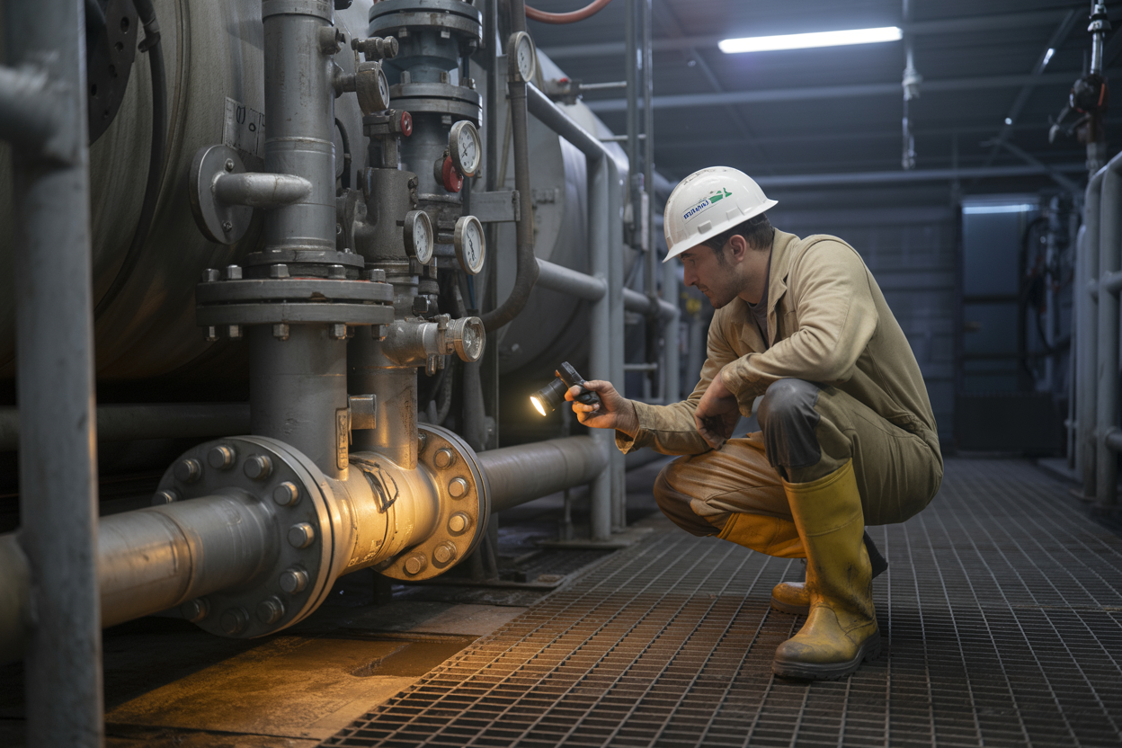
Staying ahead of problems on a mud tank transfer system comes down to what you do every single day before the pumps start spinning. A solid daily inspection routine is the difference between a minor fix during a planned break and a full-blown shutdown in the middle of a critical drilling operation.
Here’s a practical daily inspection checklist your crew should walk through every shift:
- Pump condition: Check centrifugal and mud transfer pumps for unusual vibration, noise, or heat. Any change from normal operation is a flag worth investigating.
- Suction and discharge lines: Look for visible leaks, loose flange connections, or signs of erosion along pipe runs.
- Valves and actuators: Operate each valve through its full range of motion to confirm it opens and closes cleanly without sticking or bypassing.
- Tank levels and fluid properties: Confirm fluid levels are consistent with the previous shift’s readings. Unexpected drops can mean leaks you haven’t spotted yet.
- Agitators and mixing equipment: Listen for bearing noise and check seal areas for leakage. Agitators run constantly, so they wear faster than most people expect.
- Electrical connections and control panels: Look for moisture intrusion, loose terminals, or tripped breakers on variable frequency drives and motor control centers.
- Strainer baskets: Pull and inspect suction strainers for plugging or damage. A partially blocked strainer quietly starves your pump and shortens its life.
Assign a specific crew member to own this checklist each shift. When inspection is everyone’s responsibility, it often ends up being nobody’s. A single point of accountability means problems get caught and logged consistently.
Cleaning Procedures to Prevent Buildup and Blockages
Drilling fluid is designed to carry solids in suspension, which is exactly what makes mud tank maintenance so demanding. Barite settling, weighted mud caking onto tank bottoms, and solids packing into dead-leg sections of piping are all normal consequences of how these systems work. The key is keeping buildup from reaching a point where it restricts flow, damages equipment, or contaminates the active mud system.
Tank Cleaning
Tank cleaning schedules depend on the mud weight and type being run. Heavier muds and oil-based systems need more frequent attention.
| Mud Type | Recommended Tank Cleaning Interval |
|---|---|
| Water-Based, Low Weight | Every 2–4 weeks or at bit trips |
| Water-Based, High Weight | Weekly or at each major bit trip |
| Oil-Based / Synthetic | At each casing point or as solids accumulate |
| Completion/Brine Systems | After every use before switchover |
When cleaning tanks, always follow confined space entry procedures. These are enclosed environments with poor ventilation, potential hydrogen sulfide exposure, and slip hazards from residual fluid. No shortcuts here.
Tank cleaning steps:
- Pump down the tank as low as practical using transfer pumps.
- Use high-pressure wash-down hoses to break up settled solids along the bottom and corners.
- Direct washings to the reserve pit or designated waste containment area — never onto the rig floor or into active tanks.
- Inspect tank internals, including baffles, suction boots, agitator mounts, and weir plates, while the tank is accessible.
- Check for corrosion pitting on steel surfaces and apply protective coating where needed.
Piping and Manifold Cleaning
Dead-leg piping — sections that don’t flow regularly — is where solids settle and pack hardest. Rotate your transfer routes periodically to flush these sections. During mud changes or system cleanouts, circulate clean water or compatible displacement fluid through every line to clear out residual drilling fluid before it dries and locks up.
Pay attention to:
- Suction manifold dead ends: Flush these manually if they can’t be incorporated into the normal circulation route.
- Jumper hoses and flexible connections: Clear these completely when switching mud systems to avoid cross-contamination.
- Mixing hoppers and jet lines: Run clean water through hopper lines after any chemical or barite addition to prevent caking at the nozzle.
Replacing Wear Parts Before They Cause Unplanned Shutdowns
The most expensive repair on a drilling rig is always the one nobody planned for. Wear parts in a mud tank transfer system — pump liners, impellers, mechanical seals, packing, and valve seats — degrade gradually, and that gradual degradation is something you can actually plan around if you pay attention to it.
High-Wear Components and When to Replace Them
| Component | Wear Indicators | Typical Replacement Trigger |
|---|---|---|
| Centrifugal Pump Impeller | Reduced flow rate, cavitation, vibration | 20–30% reduction in rated performance |
| Mechanical Seals | Visible fluid leakage at shaft | Any active leak — replace immediately |
| Pump Packing | Dripping at stuffing box | Excessive drip beyond adjustable range |
| Valve Seats and Trim | Bypassing fluid, unable to fully close | When valve fails to isolate completely |
| Suction Strainer Screens | Visible damage, deformation | Physical damage or blocking that can’t be cleared |
| Agitator Shaft Seals | Fluid migration along shaft | Any visible leakage at seal housing |
| Flexible Couplings | Cracking, vibration transfer to shaft | Visible cracking or abnormal vibration |
| V-Belt Drives | Fraying, glazing, slip | At first sign of wear — belts are cheap |
A parts replacement philosophy based on condition monitoring beats one based purely on fixed time intervals. Running vibration analysis on centrifugal transfer pumps, tracking motor amp draw over time, and logging flow meter performance can all give you objective data to decide when a component is actually ready to be swapped out — not just when a calendar says so.
Building a Rig Spare Parts Strategy
Keep critical spares on location at all times. Your supply chain is not your insurance policy when you’re 60 miles offshore or two hours from the nearest parts supplier.
Minimum recommended on-location spares for a rig mud system:
- At least one complete mechanical seal kit per pump model on location
- Impeller and wear ring sets for each centrifugal pump size
- Full set of replacement V-belts for all belt-driven equipment
- Spare suction strainer screens
- Gasket sets for all flanged connections in the transfer manifold
- One spare complete centrifugal pump if the rig schedule justifies it
Prebuilt pump exchanges — where a spare pump is fully dressed and ready to drop in — can cut repair time from hours to under 30 minutes. For rigs running tight drilling schedules, this is worth every dollar.
Keeping Accurate Maintenance Records for Better Decision-Making
There’s a pattern that shows up on rigs that struggle with equipment reliability: maintenance gets done but never documented. Crews rotate, institutional knowledge walks off the rig at shift change, and the next team has no baseline to work from. Accurate maintenance records solve that problem.
What to Track and Why
Good maintenance records for a drilling fluid transfer system should capture:
- Date and time of each inspection or service event
- Specific equipment serviced (pump number, tank designation, valve ID)
- Condition found (what was observed before service)
- Work performed (exactly what was done, including part numbers and quantities)
- Condition after service (performance test results, leak check status)
- Name of the technician who did the work
- Next service due (based on run hours, calendar, or condition criteria)
Using Records to Spot Trends
Raw records are useful. Analyzed records are powerful. When you have six months of pump service data, you can see that Pump #3 is chewing through mechanical seals twice as fast as the others — which tells you there’s an alignment issue, a vibration problem, or a suction condition that’s accelerating wear. Without the records, you just know the pump keeps leaking.
A few practical ways to turn records into decisions:
- Track mean time between failures (MTBF) for each pump. Declining MTBF on a specific unit is an early warning sign.
- Compare parts consumption across similar equipment. Outliers deserve investigation.
- Log operational hours alongside service events to build realistic service interval targets for your specific conditions.
- Note fluid properties at the time of service. High-density or corrosive mud programs accelerate wear and should shift your service intervals accordingly.
Digital vs. Paper Records
Paper-based logs still work, but digital maintenance management systems offer real advantages for mud tank maintenance best practices on larger rigs or multi-rig fleets.
| Feature | Paper Logs | Digital CMMS |
|---|---|---|
| Accessibility at shift change | Limited to physical location | Available on any device with access |
| Trend analysis | Manual, time-consuming | Automated reporting and charts |
| Work order generation | Manual | Automated triggers based on schedules |
| Audit trail | Dependent on legibility | Complete and searchable |
| Integration with spare parts inventory | None | Can auto-flag low stock on reorder |
Even if a full computerized maintenance management system (CMMS) isn’t in place, a structured spreadsheet shared across the rig team is a significant improvement over scattered paper logs that get lost between crew changes. The goal is simple: make sure the next person who touches that equipment knows exactly what the last person found.
Troubleshooting Common Mud Tank Transfer System Problems
Diagnosing and Fixing Low Flow Rate Issues
Low flow rates are one of the most common headaches on any rig running mud tank transfer systems, and tracking down the root cause fast can save you hours of downtime. When your flow drops unexpectedly, work through these possibilities in order:
Check the obvious stuff first:
- Suction line blockages from solids buildup or debris
- Partially closed valves that someone forgot to reopen
- Worn or damaged impellers reducing pump output
- Air entrainment in the suction line pulling performance down
- Mud weight that’s crept higher than your pump is rated to handle
Step-by-step diagnostic approach:
- Verify valve positions — Walk the entire line and confirm every valve is where it should be. This sounds basic, but misplaced valve handles cause a surprising number of low-flow calls.
- Check suction pressure — Install a gauge at the pump suction if one isn’t already there. Readings below -4 PSI typically point to a blockage or a suction line that’s too small for your current flow demand.
- Inspect strainers and screens — Mud tank suction strainers clog fast, especially when running weighted muds with high barite content. Pull and clean them before going further.
- Measure pump RPM against expected output — If the pump is spinning at the right speed but output is low, the impeller wear rings are probably the culprit.
- Check for recirculation — A failed check valve can allow mud to cycle back through the system instead of transferring forward, giving you the illusion of flow without actual movement between tanks.
| Symptom | Most Likely Cause | Quick Fix |
|---|---|---|
| Gradual flow decline | Strainer clogging | Clean or replace strainer |
| Sudden flow drop | Valve closed or line blocked | Walk the line, check valves |
| Flow drops with RPM increase | Cavitation developing | Check suction conditions |
| Inconsistent flow rate | Air entrainment | Inspect suction line fittings |
| No flow, pump running | Impeller failure or blockage | Pull pump for inspection |
When you’re dealing with thick, high-viscosity drilling fluids, even small obstructions create significant flow restrictions. A partially clogged suction strainer that barely affects water will cut your mud flow rate by 30–40%. Always size your suction lines at least one pipe size larger than your discharge lines to give yourself a buffer against restriction.
Identifying Leak Sources
Leaks in drilling fluid transfer systems don’t just waste expensive mud — they create safety hazards, environmental compliance issues, and can mask other developing problems in the system. Finding them fast and fixing them right the first time matters.
Where leaks typically show up:
- Flanged connections — Gasket failures from pressure cycling and vibration are extremely common, especially on high-traffic transfer lines
- Valve packing — Stem seals on gate valves and plug valves wear out under constant use and mud abrasion
- Pump mechanical seals — These fail gradually and often show up as a slow seep before becoming a full leak
- Flexible hose connections — Hose clamps loosen from vibration, and rubber degrades from chemical exposure
- Weld seams on tank walls — Corrosion or impact damage creates pinhole leaks that start small and grow
Leak detection approach:
Running your finger along a fitting isn’t always enough, especially when mud covers everything. Here’s a more systematic approach:
- Use UV dye tracing — Add UV-reactive dye to the mud system and use a blacklight to trace where it’s migrating. This works well for finding slow leaks that are covered by dried mud.
- Pressure test sections — Isolate sections of your transfer system and apply low-pressure air or water to identify drops that indicate a leak path.
- Watch for mud weight variations — Unexplained changes in mud weight at certain tanks can indicate a leak path mixing fluids or diluting with clean water.
- Monitor pump output vs. tank levels — If your pump is moving a calculated volume but your destination tank isn’t filling at the expected rate, you have a leak somewhere in the transfer path.
Fast repair options by leak type:
| Leak Type | Temporary Fix | Permanent Repair |
|---|---|---|
| Flanged connection | Tighten bolts evenly, apply gasket sealant | Replace gasket, re-torque to spec |
| Valve packing | Tighten packing gland nut | Replace packing with correct material |
| Pinhole tank leak | Hydraulic repair compound | Weld repair or tank panel replacement |
| Hose connection | Replace clamp, reposition hose | Replace hose with correct rated assembly |
| Threaded fitting | Thread sealant tape wrap | Replace fitting with correct grade |
When repairing flanged connections on active drilling fluid transfer systems, always replace the gasket rather than just retorquing. Spiral wound gaskets rated for your operating pressure and compatible with your fluid chemistry are the right call — rubber flat gaskets just don’t hold up long-term under vibration and thermal cycling.
Keep a repair kit on the rig floor with common gasket sizes, packing material, hydraulic repair compound, and hose clamps. Waiting on a parts run for a basic fitting repair is avoidable downtime.
Resolving Pump Cavitation
When the pressure on the suction side of your pump drops below the vapor pressure of the drilling fluid, vapor bubbles form in the liquid. Those bubbles travel into higher-pressure zones inside the pump and collapse violently, releasing localized energy that physically erodes metal surfaces. In mud systems, this happens fast because drilling fluids often contain dissolved gases and entrained air that makes them more prone to vaporizing under low suction pressure.
Primary causes of cavitation in mud tank transfer systems:
- Suction line too long or too small in diameter
- Excessive pump speed for the suction conditions
- High mud viscosity creating high suction losses
- Suction lift that’s too high (pump mounted too far above the tank)
- Partially blocked strainer or valve restricting flow to pump inlet
- Gas-cut mud coming in from the wellbore
- High mud temperature reducing the fluid’s resistance to vaporization
How to fix cavitation:
Address suction conditions first:
- Shorten suction lines where possible and eliminate unnecessary elbows
- Increase suction line diameter to reduce velocity and friction losses
- Lower the pump mounting height to reduce static suction lift — keep pumps as close to tank fluid level as your rig layout allows
- Clean suction strainers immediately
Adjust pump operation:
- Reduce pump speed — cavitation often disappears when you drop RPM by 10–15%
- If you’re running centrifugal transfer pumps, check that you’re operating within the pump curve’s recommended range for your current fluid density
Treat the fluid:
- If gas-cut mud is causing cavitation, prioritize degassing before transferring — run your degasser until Marsh funnel viscosity and density readings stabilize
- Adjust fluid temperature if high heat is contributing to vapor pressure issues
Cavitation damage assessment:
| Damage Level | Signs | Action Required |
|---|---|---|
| Early stage | Noise, slight performance drop | Fix suction conditions immediately |
| Moderate | Visible impeller pitting, 10–20% flow loss | Fix conditions, inspect and measure impeller |
| Severe | Major flow loss, noise, vibration | Replace impeller and check ring before returning to service |
| Critical | Casing damage or cracking | Full pump replacement, root cause analysis |
Don’t make the mistake of just replacing impellers without fixing the suction conditions that caused the cavitation. You’ll burn through replacement parts fast and still have an underperforming system.
Addressing Valve Failures
Common valve failure modes in drilling mud systems:
- Stuck open or stuck closed — Solids from weighted mud, barite, or LCM material pack around valve seats and stems, preventing full operation
- Partial closure — The valve appears closed but passes fluid due to seat erosion or debris lodged in the seating surface
- Stem failure — The valve stem shears or breaks, leaving the disc or gate in whatever position it was in when the failure occurred
- Actuator failure (automated valves) — Pneumatic or electric actuators lose signal, air supply, or power, leaving valves in an indeterminate position
- Backflow through check valves — Failed check valves allow reverse flow, contaminating tanks or causing pressure surges in the system
Diagnosing valve problems:
Physical inspection — Check valve handle or actuator position against the actual gate or disc position. On gate valves, count the turns from full-closed position and compare against the valve’s rated turn count.
- Downstream pressure check — A closed valve with pressure on the downstream side means it’s passing fluid. Install a pressure gauge or crack a downstream bleed point slightly.
- Flow monitoring — Use tank level gauges and flow meters to track where fluid is actually moving versus where you expect it to move.
- Thermal imaging — On larger systems, an infrared camera can identify valves that are passing hot fluid through supposedly closed positions, showing up as temperature differentials in the line.
Repair vs. replace decisions:
| Valve Type | Common Failure | Repair Feasibility | Typical Action |
|---|---|---|---|
| Gate valve | Stem wear, seat erosion | Moderate — repack and regrind seat | Repair if seat is regrindable, replace if worn through |
| Plug valve | Solids packing, seal wear | Good — replace seals, clean plug | Clean, lubricate, replace seals |
| Check valve | Spring failure, disc wear | Limited — replace internals | Replace check valve assembly |
| Butterfly valve | Seat damage, disc erosion | Moderate — replace seat and disc | Replace worn components |
| Actuated ball valve | Actuator failure | Good — replace actuator | Swap actuator, test operation |
Preventing future valve failures:
- Flush valve bodies with clean fluid before extended shutdowns to prevent solids from hardening around seats and stems
- Exercise valves regularly — a valve that sits in one position for weeks is a valve that will stick when you need it most
- Use valve types matched to your fluid — high-solids mud systems do better with full-bore ball valves or plug valves than with gate valves, which tend to trap solids in the bonnet cavity
- Maintain a valve inventory on the rig that covers your most critical positions so that a failed valve doesn’t become a multi-day wait for parts
- Tag all valves clearly and keep your valve position diagrams updated — misidentified valves create the wrong diagnosis every time
On automated mud transfer systems, build in manual override capability at every critical valve position. Actuator failures happen, and having to shut down mud transfer because an electronic valve won’t respond to a signal is an entirely avoidable problem.
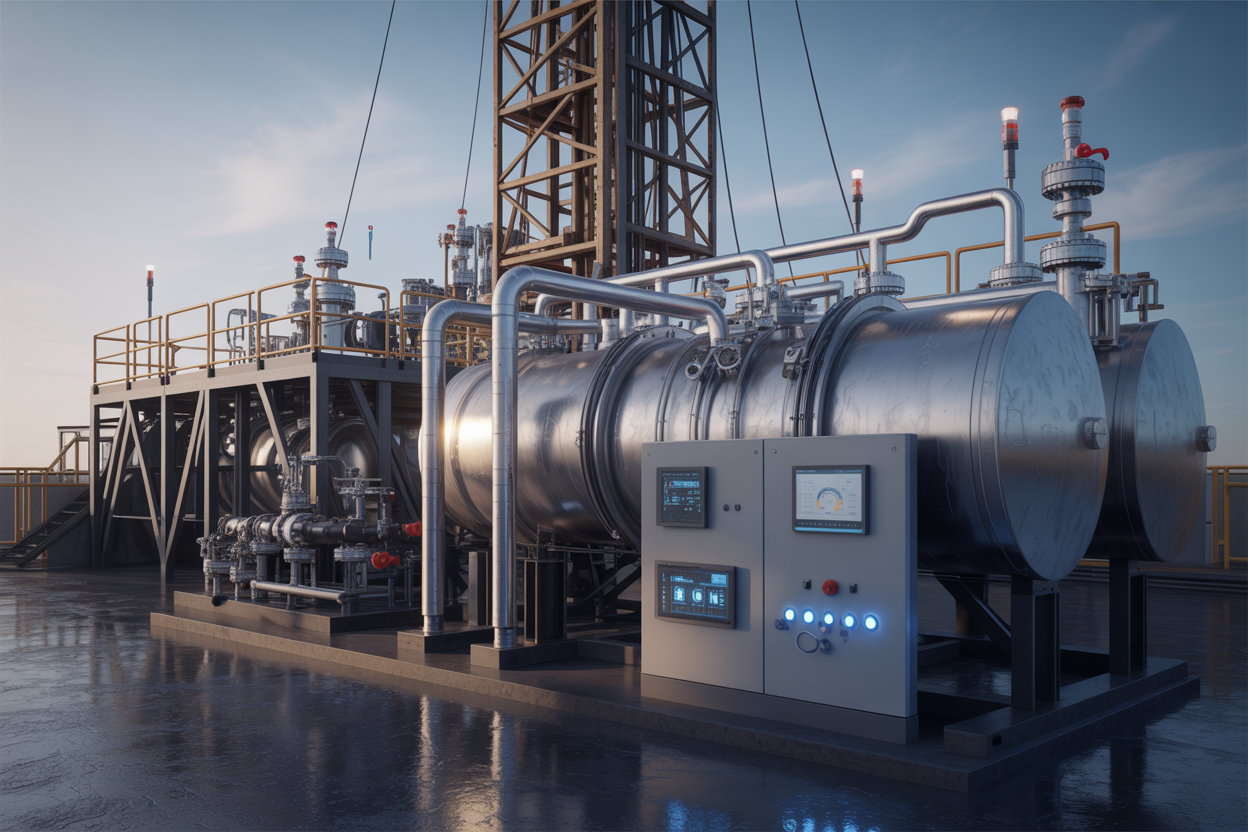
Emerging Technologies Improving Mud Tank Transfer Systems
Automation and Remote Monitoring for Smarter Transfer Control
The days of a derrickman manually walking the tank line to check levels and adjust valves are quickly becoming a thing of the past. Modern rig mud tank systems are getting a serious upgrade through automation platforms that give operators full visibility and control — often from a single touchscreen panel or even a handheld device.
Today’s automated transfer control systems typically include:
- Automated valve actuators that open and close transfer lines based on programmed logic or real-time commands
- Level sensors and ultrasonic transducers mounted in each tank compartment that feed continuous level data to a central PLC (Programmable Logic Controller)
- Flow meters integrated into the transfer lines to track exactly how much drilling fluid is moving between tanks at any given moment
- Remote monitoring dashboards that display tank levels, pump status, flow rates, and alarm conditions in real time
What Remote Monitoring Actually Changes on the Rig Floor
When you wire up a mud tank transfer system with remote monitoring, you’re not just adding convenience — you’re removing human error from the equation in a big way. An automated system can detect an overfill condition and shut down the transfer pump in milliseconds. A person walking the tanks might catch it in two minutes, if they’re lucky.
Some advanced mud tank technology packages now tie directly into the rig’s overall SCADA (Supervisory Control and Data Acquisition) system. This means drilling fluid transfer system data lives alongside other critical rig parameters — hook load, standpipe pressure, rotary torque — giving the driller a complete operational picture without switching screens.
Key automation benefits worth knowing:
| Benefit | Traditional Setup | Automated Setup |
|---|---|---|
| Transfer monitoring | Manual gauge checks | Continuous real-time data |
| Alarm response | Depends on personnel | Instant automated shutdown |
| Data logging | Paper records or manual entry | Automatic timestamped logs |
| Remote access | Not possible | Tablet/smartphone capable |
| Valve operation | Manual turn or local actuator | Remote command or auto-sequence |
SCADA-integrated oilfield mud system components can also push alerts via SMS or email to off-site engineers, which is especially valuable on unmanned or minimally staffed locations during non-drilling periods.
Advanced Pump Technologies That Reduce Energy Consumption
Mud pump transfer systems have traditionally been power-hungry workhorses — reliable, yes, but not exactly efficient. That’s changing fast. A new generation of pump technologies is cutting energy consumption significantly without sacrificing the flow rates and pressures that drilling fluid transfer systems demand.
Variable Frequency Drives (VFDs) Are Leading the Charge
Variable Frequency Drives are probably the single biggest advancement in pump energy efficiency for drilling mud transfer equipment right now. A VFD lets you dial the motor speed to exactly what the job needs rather than running it flat out all the time.
Here’s why that matters in practice:
- A centrifugal transfer pump running at 70% speed consumes roughly 35% less energy than one running at full speed (thanks to the affinity laws of fluid dynamics)
- Softer starts mean less mechanical stress on the pump, motor, and connected piping
- Flow rate can be matched precisely to transfer demand, reducing overflow risks and fluid agitation
Many newer rigs are specifying VFD-equipped transfer pumps as standard hardware, not an optional upgrade.
Submersible and Magnetic Drive Pumps
Beyond VFDs, submersible transfer pumps are gaining traction in mud tank layout designs where space is tight and suction lift is a concern. By placing the pump directly inside the tank, you eliminate the suction head problem entirely and reduce the risk of cavitation — one of the most common causes of early pump failure in drilling fluid transfer systems.
Magnetic drive pumps eliminate the mechanical seal entirely, which is a game changer for abrasive or chemically aggressive drilling fluids that chew through conventional seal materials quickly.
Comparing Pump Technologies for Mud Transfer Applications
| Pump Type | Best Use Case | Energy Efficiency | Seal/Leak Risk | Cost |
|---|---|---|---|---|
| Centrifugal with VFD | High-volume transfer between large tanks | High | Low-Medium | Medium |
| Submersible centrifugal | Space-constrained tanks, low suction head | Medium-High | Low | Medium |
| Magnetic drive centrifugal | Aggressive or abrasive fluids | Medium | Very Low | High |
| Progressive cavity (VFD) | High-viscosity fluids, shear-sensitive muds | Medium | Medium | Medium-High |
| Air-operated diaphragm | Low-flow, remote areas, no power available | Low | Very Low | Low |
Choosing the right pump for your specific mud tank transfer system setup comes down to fluid properties, transfer volume, available power, and space constraints. There’s no universal winner, but the shift toward VFD-driven centrifugal pumps as the backbone of most systems is hard to argue with from an efficiency standpoint.
Data-Driven Predictive Maintenance for Fewer Unexpected Failures
Reactive maintenance — fixing things after they break — has always been expensive on a drilling rig. Every hour of unplanned downtime waiting on a pump rebuild or a failed valve costs far more than the part itself. Predictive maintenance flips that model on its head by using real-time data to spot problems before they knock a system offline.
For mud tank transfer systems specifically, predictive maintenance programs are built around a few core data streams:
- Vibration analysis on pump motors and impellers to catch bearing wear, cavitation damage, or imbalance early
- Temperature monitoring on motor windings and pump housings to flag overheating conditions
- Flow rate trending — a pump that’s delivering 10% less flow than it was last week at the same speed is telling you something is wrong
- Power draw monitoring — abnormal spikes or drops in motor current consumption often signal mechanical issues before any physical symptom appears
- Differential pressure across filters and screens to predict when cleaning or replacement is needed
How Machine Learning is Changing the Game
Some of the more advanced mud tank technology platforms are layering machine learning algorithms on top of this sensor data. Instead of just triggering an alarm when a value crosses a threshold, the system learns the normal operating signature of each pump and valve assembly and flags deviations that a static threshold would miss entirely.
For example, a pump might run at slightly elevated vibration every time a specific tank is almost empty due to suction vortexing. A threshold-based alarm would fire constantly and get ignored. A machine learning model learns that pattern and stops crying wolf, while still catching the abnormal vibration that means a bearing is actually failing.
Practical Steps Toward Predictive Maintenance on Mud Tank Systems
Getting a predictive maintenance program off the ground doesn’t require a complete digital overhaul of the rig overnight. A phased approach works well:
- Start with vibration and temperature sensors on your most critical transfer pumps — the ones whose failure causes the most downtime
- Establish baselines over 30-60 days of normal operation before trying to act on the data
- Connect sensor data to your CMMS (Computerized Maintenance Management System) so work orders can be triggered automatically when conditions are met
- Train the rig crew to review trend data during handovers, not just respond to alarms
- Expand coverage to secondary pumps, actuated valves, and agitators once the process is proven
ROI of Predictive vs. Reactive Maintenance
| Maintenance Approach | Average Cost per Failure Event | Unplanned Downtime | Component Lifespan |
|---|---|---|---|
| Reactive | High (emergency parts, labor, rig time) | Significant | Shortened by run-to-failure |
| Preventive (time-based) | Medium (some unnecessary replacements) | Reduced | Moderate improvement |
| Predictive (data-driven) | Low (planned work, no emergency premium) | Minimal | Maximized |
The data makes a strong case, and the oilfield industry is paying attention. Operators who have rolled out predictive maintenance programs on their drilling mud transfer equipment consistently report reductions in unplanned downtime of 25-40%, along with extended component life across pumps, motors, and valve assemblies. When you factor in what a single day of rig downtime costs in a deepwater or complex well environment, the technology pays for itself quickly.
Conclusion
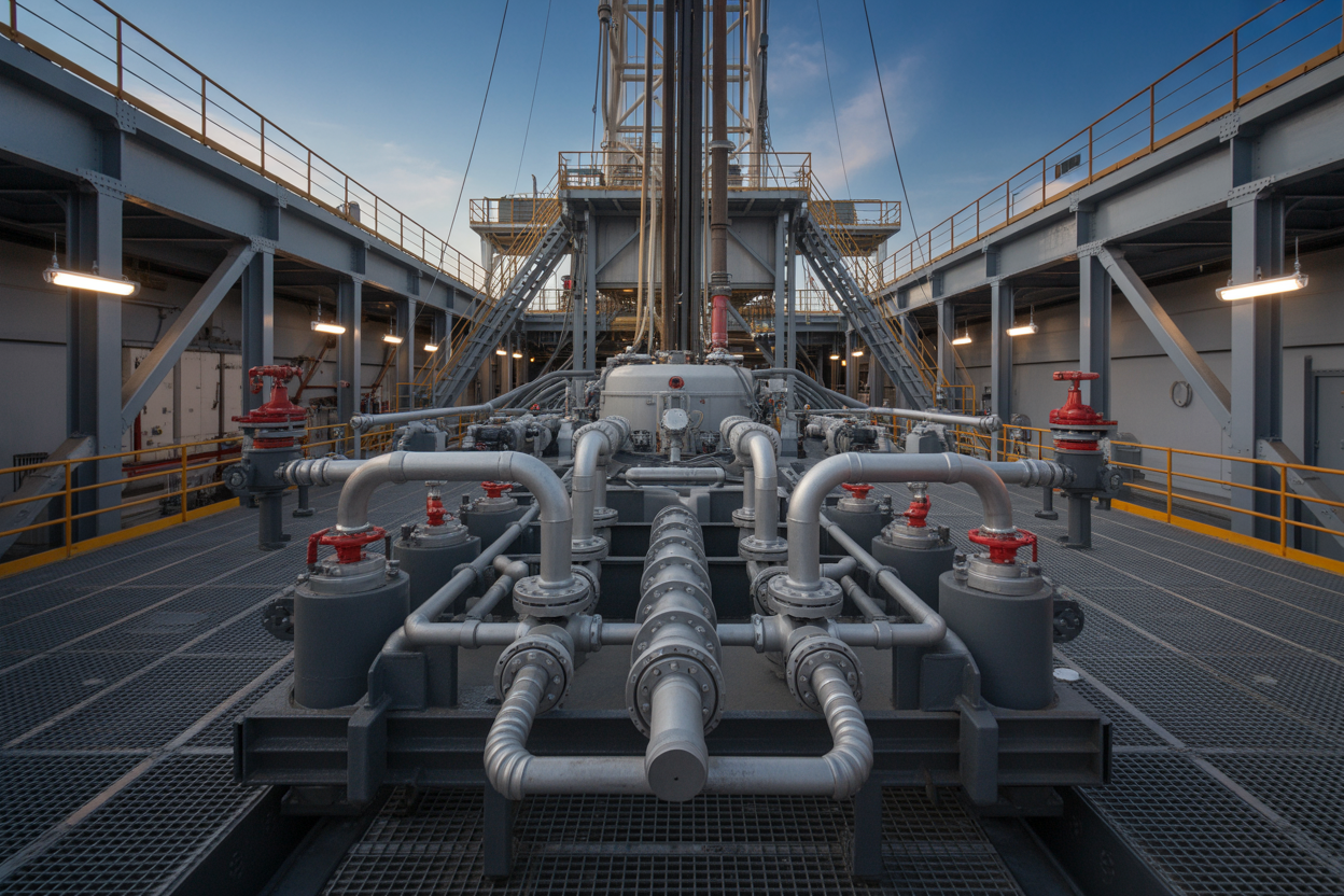
Mud tank transfer systems are the backbone of any well-run drilling operation. From understanding the basic types and hardware involved, to designing smart layouts, running systems safely, and keeping up with maintenance — every piece of the puzzle plays a role in keeping your rig running smoothly and efficiently. Throw in the ability to troubleshoot problems quickly, and you’ve got a solid foundation for minimizing downtime and avoiding costly headaches out in the field.
The good news is that the technology behind these systems keeps getting better. Smarter monitoring tools, more reliable components, and improved design approaches mean there’s always room to upgrade and optimize how your rig handles drilling fluids. Take the time to review your current setup against the best practices covered in this guide, identify any weak spots, and make the changes that’ll keep your operation running at its best. A well-designed, properly maintained mud tank transfer system isn’t just a technical checkbox — it’s a real competitive advantage on any rig.


